INSTALLATION
Installing Blower Accessory GA3450TA (Cont.)
13
INSTALLATION
Continued
For Built-In Installation
![]() WARNING: A licensed electrician must connect the wiring harness to electrical supply following all local codes.Electricianmustprovideaclampontheboxcover to secure the wiring. Wiring should be routed through the bushing in the hole on the outer casing of fireplace.
WARNING: A licensed electrician must connect the wiring harness to electrical supply following all local codes.Electricianmustprovideaclampontheboxcover to secure the wiring. Wiring should be routed through the bushing in the hole on the outer casing of fireplace.
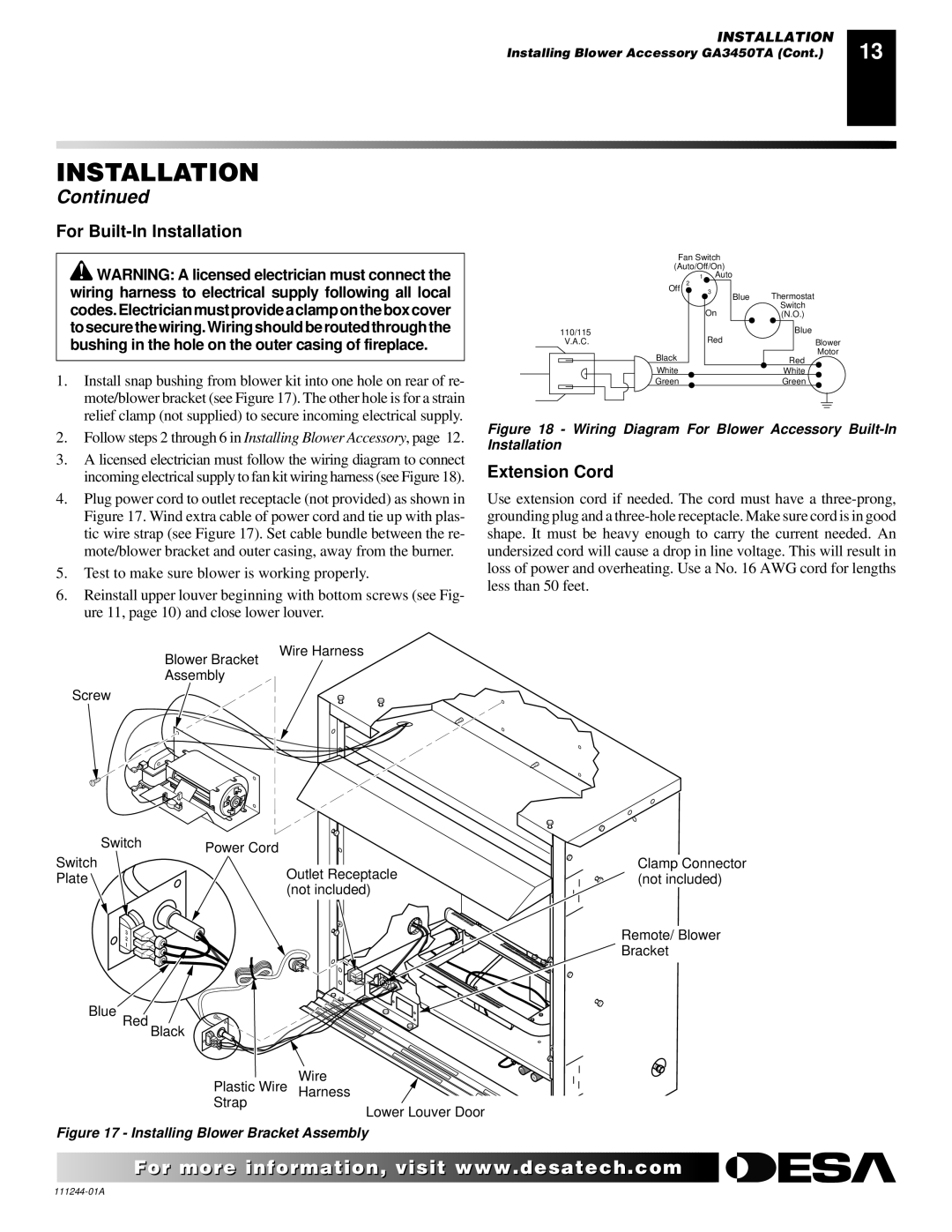
1.Install snap bushing from blower kit into one hole on rear of re- mote/blower bracket (see Figure 17). The other hole is for a strain relief clamp (not supplied) to secure incoming electrical supply.
2.Follow steps 2 through 6 in Installing Blower Accessory, page 12.
| Fan Switch |
|
|
|
|
|
| ||||
| (Auto/Off/On) |
|
|
|
|
|
| ||||
|
| 1 Auto |
|
|
|
|
|
| |||
| Off | 2 |
|
|
|
|
|
|
|
|
|
|
| 3 | Blue |
| Thermostat | ||||||
|
|
| On |
|
|
| Switch | ||||
|
|
|
|
|
| (N.O.) | |||||
110/115 |
|
| Red |
|
|
|
| Blue | |||
V.A.C. |
|
|
|
| Blower | ||||||
| Black |
|
|
|
|
|
|
|
| Motor | |
|
|
|
|
|
|
| Red |
| |||
| White |
|
|
|
|
|
| White |
| ||
| Green |
|
|
|
|
|
| Green | |||
Figure 18 - Wiring Diagram For Blower Accessory Built-In Installation
3.A licensed electrician must follow the wiring diagram to connect incoming electrical supply to fan kit wiring harness (see Figure 18).
4.Plug power cord to outlet receptacle (not provided) as shown in Figure 17. Wind extra cable of power cord and tie up with plas- tic wire strap (see Figure 17). Set cable bundle between the re- mote/blower bracket and outer casing, away from the burner.
5.Test to make sure blower is working properly.
6.Reinstall upper louver beginning with bottom screws (see Fig- ure 11, page 10) and close lower louver.
Extension Cord
Use extension cord if needed. The cord must have a
Blower Bracket
Assembly
Screw
Wire Harness
| Switch | Power Cord |
Switch |
| |
| Outlet Receptacle | |
Plate |
| |
| (not included) | |
|
|
3 2 1
Blue Red
Black
Wire
Plastic Wire Harness
Strap
Lower Louver Door
Figure 17 - Installing Blower Bracket Assembly
I
H
| O |
NO | FF |
Clamp Connector (not included)
Remote/ Blower Bracket
For more![]()
![]()
![]() visit www.
visit www.![]()
![]()
![]() .com
.com![]()
![]()
![]()
![]()
![]()