Manuals
/
MGE UPS Systems
/
Computer Equipment
/
Power Supply
MGE UPS Systems
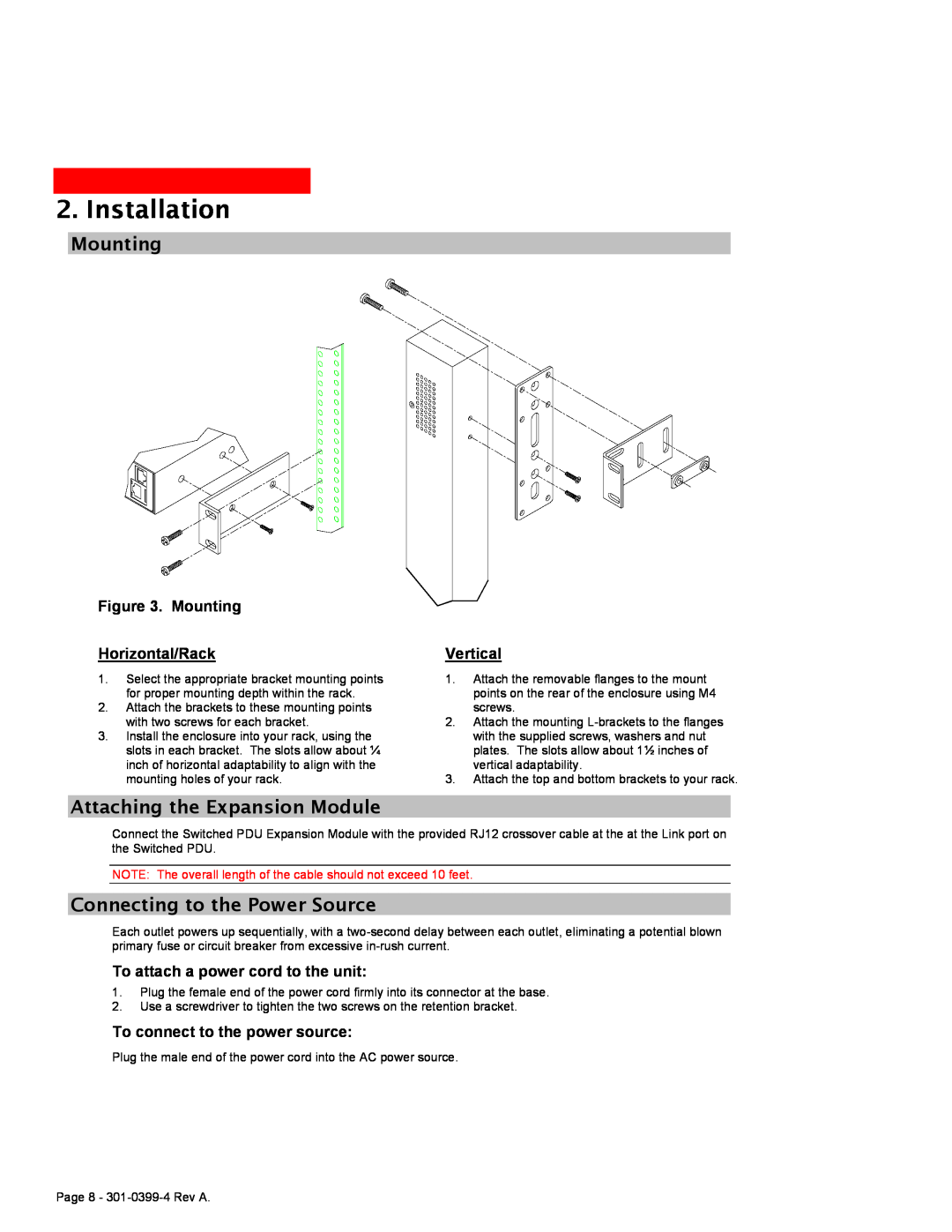
Switched PDU Attaching the Expansion Module, Mounting Horizontal/Rack
Models:
Switched PDU
1
8
62
62
Download
62 pages
5.96 Kb
5
6
7
8
9
10
11
12
Specifications
Install
Password
Setting the trap timer
LED Indicators
Administrative Command Summary
Connecting Devices
Configuration
To reset the trap destination
Setting SSL access level
Page 8
Image 8
Page 7
Page 9
Page 8
Image 8
Page 7
Page 9
Contents
Switched PDU Installation and user manual
E T N I N U E H T
Instructions
Dangerous Voltage
Protective Grounding Terminal
Life-Support Policy
Contents
INSTALLATION
GETTING STARTED
OPERATIONS
user account prior to attachment to your network
1. Getting Started
Quick Start Guide
Additional Required Items
2. Installation
Standard Accessories
Equipment Overview
Figure 1. Unit Views
1 Power Input 2 Input Current LED 3 Ethernet / RS232 Ports
4 Temperature / Humidity Ports
Safety Precautions
Installing the Power Input Retention Bracket
Figure 2. Retention Bracket assembly
To install the power input retention bracket
Connecting to the Power Source
To attach a power cord to the unit
To connect to the power source
Mounting
Connecting Devices
Connecting the Sensors
Connecting to the Unit
Serial RS232 port
Page
3. Operations
I NTERFACES
HTML I NTERFACE
C OMMAND L INE I NTERFACE
Usernames and Passwords
3. Operations
Interfaces
Outlet Naming and Grouping
To log in by HTML
HTML Interface
Figure 4. Example HTML page Logging In
Outlet Control
Individual
Group
Outlet State/Control State Field Values
Configuration
Environmental Monitoring
Input Load
Sensors
Network
Telnet/SSH
HTTP/SSL
Setting the IP address, subnet mask or gateway
Serial Ports
Setting the HTTP authentication method
Setting SSL access level
Setting the data-rate for the serial ports
Outlets
Groups
Users
Changing a user password
Changing a user’s access privilege level
Adding and Deleting outlet access
Adding and Deleting group access
Adding and Deleting serial port access
SNTP
SNMP
Setting the filename for upload
Testing the FTP upload configuration
Command Line Interface
Tools
Restart
Logging In
Operations Command Summary
Administrative Command Summary
To display the names of commands that you may execute
Administrative Command Summary continued
Operations Commands
Rebooting outlets
To reboot one or more outlets
Turning outlets on
Displaying outlet status
To display on/off status of one or more outlets
Displaying accessible outlets
To display accessible outlets
Displaying accessible groups
To display accessible groups
Displaying accessible serial ports
To display accessible serial ports
Connecting to a serial device
Displaying infeed status
Displaying the status of the Environmental Monitor
To display the status of the Environmental Monitor
Starting a new session
To start a new session
Administration Commands
User Administration
Creating a user account
To create a user account
Changing a password
To change a password
Setting user access level privileges
To set the access level privilege for a user
Displaying the access privilege levels
To display user access privilege levels
Adding outlet access to a user
To grant outlet access to a user
Deleting outlet access for a user
To delete outlet access for a user
Adding group access to a user
To grant group access to a user
Group Administration
Displaying user outlet, group and serial port access
To display user outlet, group and serial port access
Creating a group name
Outlet Administration
Adding an outlet to a group
To add an outlet to a group
Deleting an outlet from a group
Setting the outlet wakeup state
To set the wakeup state
Displaying outlet information
To display outlet information
Serial Port Administration
Setting the serial ports data-rate
Enabling or disabling active signal checking for serial connections
To enable or disable active signal checking for serial connections
System Administration
Displaying system configuration information
To display system configuration information
Creating a location description
Creating a descriptive tower name
To create a tower name
Displaying tower information
To display tower information
TCP/IP Administration
To perform a warm boot
Setting the IP address
Setting the subnet mask
HTTP Administration
Displaying network configuration information
To display network configuration information
To enable or disable HTTP support
Telnet Administration
FTP Administration
To set the HTTP authentication method
To enable or disable Telnet support
Setting the FTP Password
To set the FTP password
Setting the filename to be uploaded
Setting the filepath for the file to be uploaded
SNTP Administration
Setting the SNTP server address
Displaying SNTP configuration information
To display SNTP configuration information
Enabling and Setting up SSL Support
SSL Technical Specifications
Enabling and Setting up SSH Support
SSH Technical Specifications
SSL Command Summary
Enabling and Setting up SSL Support
SSL Technical Specifications
To enable or disable SSL support
SSH Command Summary
Enabling and Setting up SSH Support
SSH Technical Specifications
To enable or disable SSH support
SNMP Command Summary
Enabling and Setting up SNMP Support
SNMP
To enable SNMP support
To reset the trap destination
To set the trap timer
Setting the Get/Set community strings
Setting the Trap community string
SNMP Traps
Trap Summary
Tower Status traps
Infeed Status traps
Outlet Status traps
Environmental Monitor Status traps
Temperature/Humidity Sensor Status traps
Load traps
Temp traps
Humidity traps
Temp Trap
Humidity Trap
Enabling or Disabling a Status trap
Configuring Traps SNMP Trap Command Summary
To Enable or Disable a Status trap
To Enable or Disable a Load trap
Setting the Infeed Load limit
To Enable or Disable a Change trap
To Enable or Disable the Temp trap
Setting the Temperature sensor threshold limits
To Enable or Disable the Humid trap
Setting the Humidity sensor threshold limits
To set the Temperature threshold limits
Displaying trap configuration information
To display trap information
Status
WebServer1
R ESETTING TO F ACTORY D EFAULTS
5. Appendices
U PLOADING F IRMWARE
T ECHNICAL S PECIFICATIONS
Resetting to Factory Defaults
To reset to factory defaults from the HTML interface
To reset to factory defaults from the command line
To reset to factory defaults using the reset button
Technical Specifications
Power Ratings
Physical Specifications
Models Europe/Asia
LED Indicators
Data Connections
Branch Circuit Protection
RS-232 port
Page
Top
Page
Image
Contents