|
|
| INSTALLATION | |
|
|
| Continued | |
Blower Bracket Assembly | Wire Harness | |||
Screw |
| Wiring Routing Hole | ||
| in Baffle | |||
|
|
| ||
|
|
| Baffle | |
|
|
| Blower Mounting | |
|
|
| Holes | |
Switch |
|
|
| |
| Power Cord | Snap | ||
|
|
| ||
|
|
| Bushing | |
3 |
|
|
| |
2 |
|
|
| |
1 |
|
|
| |
Switch | Blue |
|
| |
Plate |
|
| ||
|
|
| ||
| Black |
|
| |
Red | Wire | Front Fan | ||
Harness | Switch | Rear Fan | ||
| ||||
|
| Cover | Switch Cover | |
Lower Louver Door
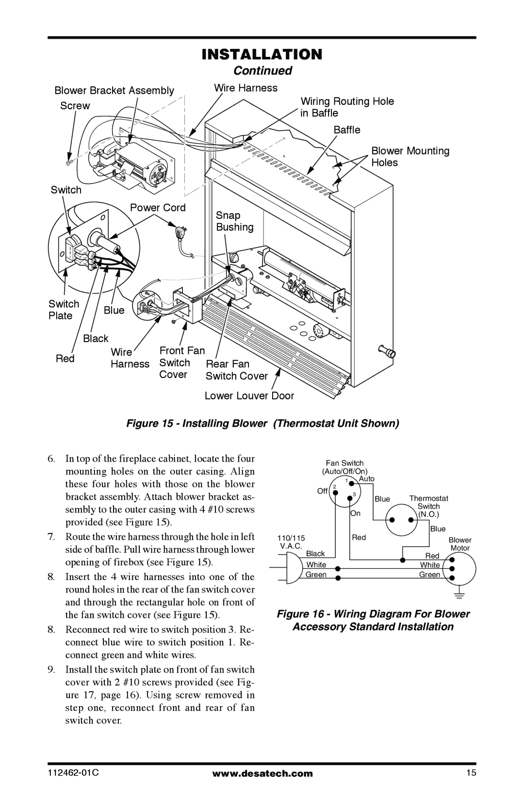
Figure 15 - Installing Blower (Thermostat Unit Shown)
6. In top of the fireplace cabinet, locate the four |
mounting holes on the outer casing. Align |
these four holes with those on the blower |
Fan Switch
(Auto/Off/On)
1Auto
| bracket assembly. Attach blower bracket as- |
| sembly to the outer casing with 4 #10 screws |
| provided (see Figure 15). |
7. | Route the wire harness through the hole in left |
| side of baffle. Pull wire harness through lower |
| opening of firebox (see Figure 15). |
8. | Insert the 4 wire harnesses into one of the |
| round holes in the rear of the fan switch cover |
| and through the rectangular hole on front of |
|
| Off | 2 |
|
|
| 3 |
|
|
| On |
110/115 | Red | ||
| V.A.C. |
| |
|
| Black |
|
|
|
| |
|
| White |
|
|
| Green |
|
Blue Thermostat
Switch
(N.O.)
Blue
Blower
Motor
Red
White
Green
the fan switch cover (see Figure 15). |
8.Reconnect red wire to switch position 3. Re- connect blue wire to switch position 1. Re- connect green and white wires.
9.Install the switch plate on front of fan switch cover with 2 #10 screws provided (see Fig- ure 17, page 16). Using screw removed in step one, reconnect front and rear of fan switch cover.
Figure 16 - Wiring Diagram For Blower
Accessory Standard Installation
www.desatech.com | 15 |
