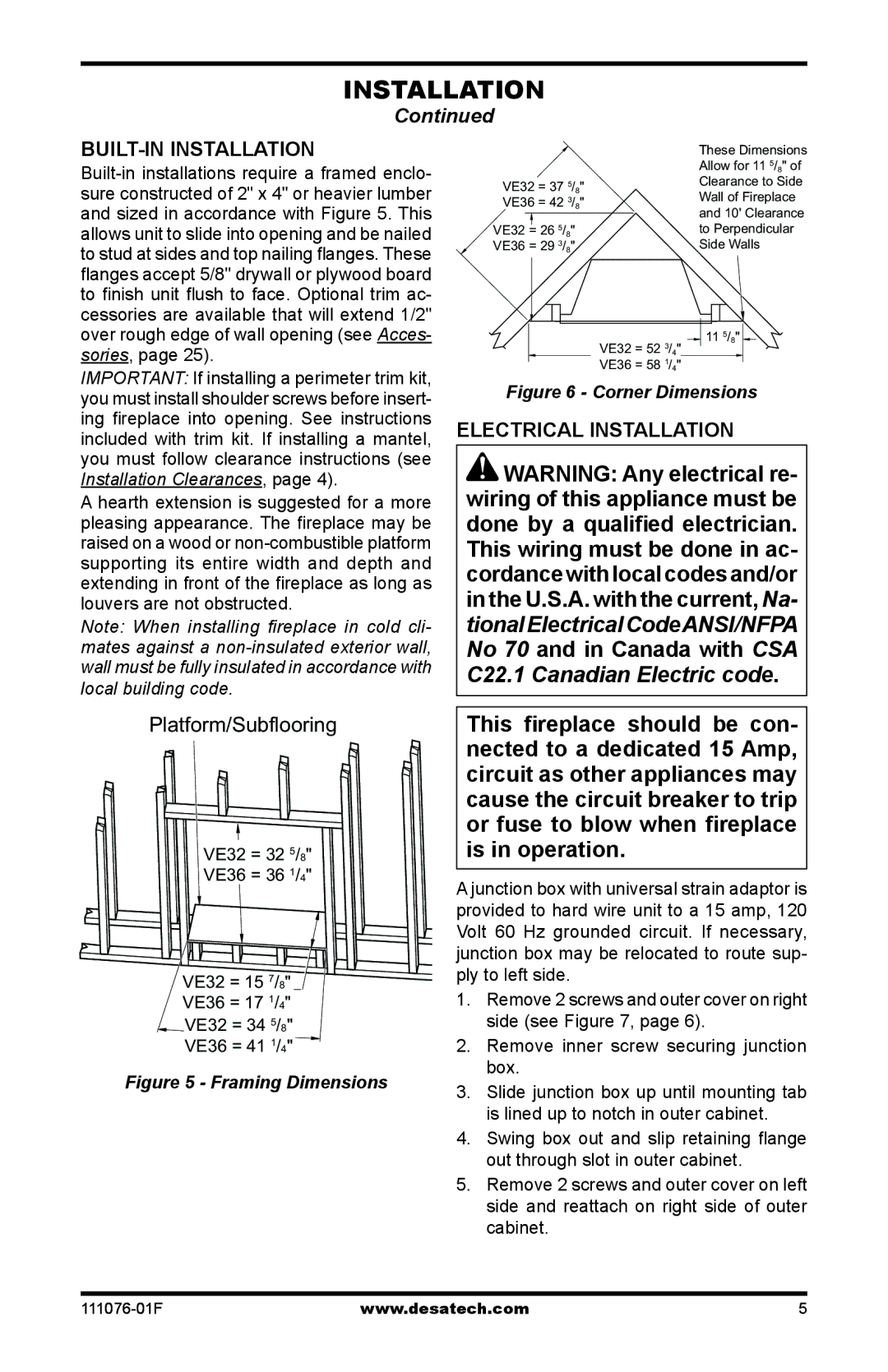
E32LB, E36L, E36LH, E32L, E32LH specifications
The Desa E32L, E32LBH, E32LH, E36LB, and E36LBH are part of a versatile range of container handling equipment designed for efficient operations in various industrial environments. These models are particularly known for their robust performance, durability, and user-friendly features, making them suitable for both indoor and outdoor applications.The Desa E32L and E32LBH are characterized by their compact designs, which allow for easy maneuverability in tight spaces. These models are equipped with advanced lifting technologies, including hydraulic systems that ensure smooth and precise lifting. The E32L model is specifically designed for lighter loads, making it ideal for warehouses and manufacturing settings where space is limited.
On the other hand, the E32LBH variant adds a height-adjustable feature, allowing operators to adapt to different working conditions without compromising stability. This flexibility makes it a favored choice in varied environments, including distribution centers where changes in load height are common.
The E32LH model stands out with its extended reach capabilities. This feature is particularly beneficial in environments where access to tall or stacked goods is necessary, enhancing productivity by minimizing the need for additional equipment. The E32LH also maintains the core benefits of the E32 series, providing reliable performance with a strong focus on operator safety.
Shifting focus to the E36LB and E36LBH, these models cater to heavier lifting tasks. The E36 series incorporates enhanced lifting capacity and stability, essential for handling bulk materials or larger pallets. The robust build and powerful hydraulic systems offer improved performance in demanding applications, ensuring that heavy loads are transported safely and efficiently.
All models in the Desa E series are integrated with ergonomic features aimed at enhancing user comfort. This includes adjustable handles and controls that reduce operator fatigue during long shifts. Furthermore, safety features such as overload protection and anti-slip surfaces are standard, ensuring that operators can work confidently without compromising safety.
In terms of technology, the E series utilizes advanced engineering that emphasizes energy efficiency and low maintenance costs. The hydraulic systems are designed for longevity, and the overall construction of these machines is aimed at withstanding harsh industrial environments.
With a commitment to innovation and efficiency, the Desa E32L, E32LBH, E32LH, E36LB, and E36LBH models reflect modern advancements in material handling technology, making them invaluable assets for businesses seeking to optimize their operational productivity and safety.

