MAINTENANCE
Continued
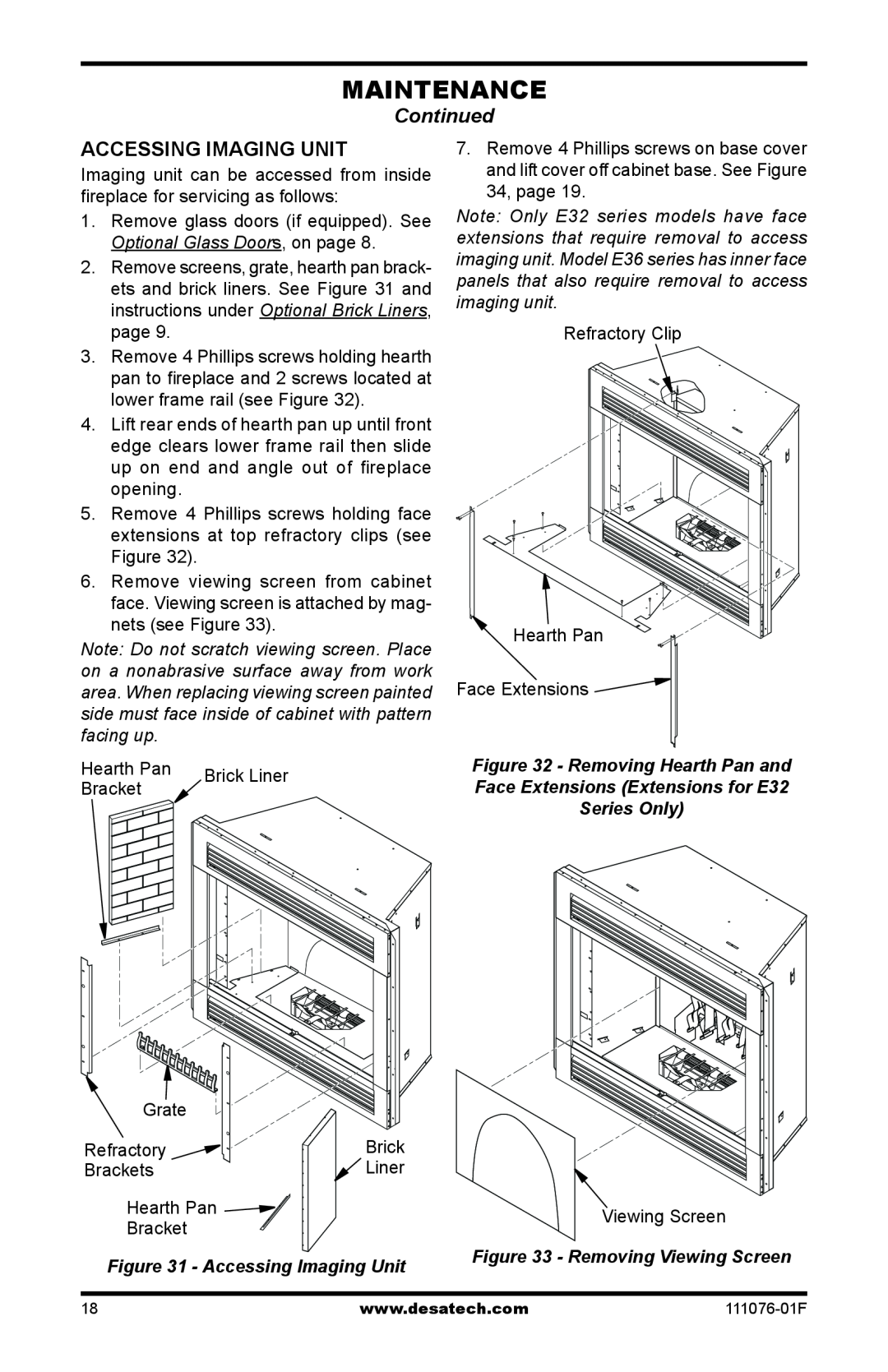
Accessing Imaging Unit
Imaging unit can be accessed from inside fireplace for servicing as follows:
1.Remove glass doors (if equipped). See Optional Glass Doors, on page 8.
2.Remove screens, grate, hearth pan brack- ets and brick liners. See Figure 31 and instructions under Optional Brick Liners, page 9.
3.Remove 4 Phillips screws holding hearth pan to fireplace and 2 screws located at lower frame rail (see Figure 32).
4.Lift rear ends of hearth pan up until front edge clears lower frame rail then slide up on end and angle out of fireplace opening.
5.Remove 4 Phillips screws holding face extensions at top refractory clips (see Figure 32).
6.Remove viewing screen from cabinet face. Viewing screen is attached by mag- nets (see Figure 33).
Note: Do not scratch viewing screen. Place on a nonabrasive surface away from work area. When replacing viewing screen painted side must face inside of cabinet with pattern facing up.
Hearth Pan | Brick Liner | |
Bracket | ||
|
Grate |
|
Refractory | Brick |
Brackets | Liner |
Hearth Pan |
|
Bracket |
|
Figure 31 - Accessing Imaging Unit
7.Remove 4 Phillips screws on base cover and lift cover off cabinet base. See Figure 34, page 19.
Note: Only E32 series models have face extensions that require removal to access imaging unit. Model E36 series has inner face panels that also require removal to access imaging unit.
Refractory Clip
![]() Hearth Pan
Hearth Pan
Face Extensions ![]()
Figure 32 - Removing Hearth Pan and
Face Extensions (Extensions for E32
Series Only)
Viewing Screen
Figure 33 - Removing Viewing Screen
18 | www.desatech.com |