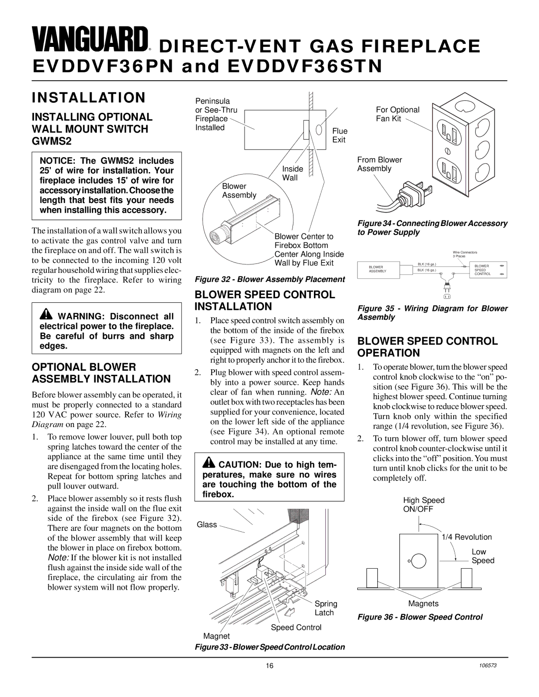
EVDDVF36PN, EVDDVF36STN specifications
Desa EVDDVF36STN and EVDDVF36PN are innovative and versatile electric heating solutions designed for modern indoor environments. These models stand out in the realm of electric heaters due to their advanced technologies, user-friendly features, and energy-efficient characteristics.One of the main features of Desa EVDDVF36STN and EVDDVF36PN is their dual fuel capability, allowing users to harness the benefits of both electric and gas heating systems. This versatility ensures that users can maintain optimal comfort levels while minimizing energy costs. The models are equipped with a powerful heating element that can efficiently manage large spaces, making them ideal for homes, workshops, or commercial applications.
In terms of technology, both the EVDDVF36STN and EVDDVF36PN are engineered with a high-efficiency heating system that utilizes radiant heat to warm rooms quickly. This technology reduces the time required to reach desired temperatures, ensuring prompt comfort for users. Additionally, the heaters incorporate digital control systems that allow for precise temperature adjustments, enabling users to tailor their heating experience to meet specific preferences.
Another significant characteristic of these models is their sleek and modern design, which blends seamlessly into various interior styles. The cabinets are constructed from durable materials, ensuring longevity and resilience against wear and tear. Both models come with a variety of finishes and colors, allowing users to choose an aesthetic that complements their space.
The Desa EVDDVF36STN and EVDDVF36PN are also equipped with safety features that prioritize user well-being. These include automatic shut-off sensors that activate in case of overheating or if the unit tips over, providing peace of mind to users.
Moreover, these electric heaters are designed with energy efficiency in mind. They have a lower carbon footprint compared to traditional heating systems, contributing positively to environmental conservation efforts. Their efficient operation not only reduces energy consumption but also translates to lower utility bills, making them an economical choice for consumers.
In conclusion, the Desa EVDDVF36STN and EVDDVF36PN electric heaters embody the perfect combination of functionality, technology, safety, and style. Their dual fuel capability, rapid heating technology, and energy efficiency make them an outstanding option for anyone looking to enhance their indoor comfort while being mindful of their environmental impact.

