SUN VALLEY STOVE COMPANY

CAST IRON STOVE AND BURNER SYSTEM

CAST IRON STOVE AND B-VENT BURNER SYSTEM ASSEMBLY

Continued

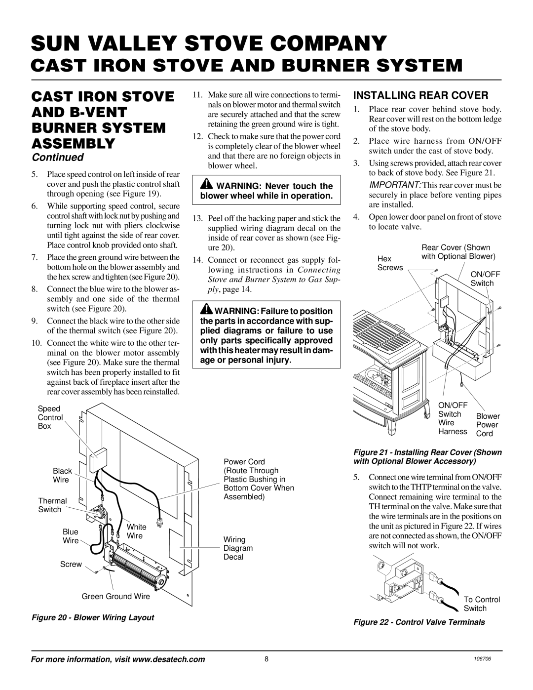
5.Place speed control on left inside of rear cover and push the plastic control shaft through opening (see Figure 19).

6.While supporting speed control, secure control shaft with lock nut by pushing and turning lock nut with pliers clockwise until tight against the side of rear cover. Place control knob provided onto shaft.

7.Place the green ground wire between the bottom hole on the blower assembly and the hex screw and tighten (see Figure 20).

8.Connect the blue wire to the blower as- sembly and one side of the thermal switch (see Figure 20).

9.Connect the black wire to the other side of the thermal switch (see Figure 20).

10.Connect the white wire to the other ter- minal on the blower motor assembly (see Figure 20). Make sure the thermal switch has been properly installed to fit against back of fireplace insert after the rear cover assembly has been reinstalled.

Speed

Control

Box

Black

Wire

Thermal

Switch

Blue

White

Wire

Wire


Screw


Green Ground Wire

Figure 20 - Blower Wiring Layout

11.Make sure all wire connections to termi- nals on blower motor and thermal switch are securely attached and that the screw retaining the green ground wire is tight.

12.Check to make sure that the power cord is completely clear of the blower wheel and that there are no foreign objects in blower wheel.

WARNING: Never touch the blower wheel while in operation.

13.Peel off the backing paper and stick the supplied wiring diagram decal on the inside of rear cover as shown (see Fig- ure 20).

14.Connect or reconnect gas supply fol- lowing instructions in Connecting Stove and Burner System to Gas Sup- ply, page 14.

WARNING: Failure to position the parts in accordance with sup- plied diagrams or failure to use only parts specifically approved with this heater may result in dam- age or personal injury.

Power Cord

(Route Through

Plastic Bushing in

Bottom Cover When

Assembled)

Wiring

Diagram

Decal

INSTALLING REAR COVER

1.Place rear cover behind stove body. Rear cover will rest on the bottom ledge of the stove body.

2.Place wire harness from ON/OFF switch under the cast of stove body.

3.Using screws provided, attach rear cover to back of stove body. See Figure 21.

IMPORTANT: This rear cover must be securely in place before venting pipes are installed.

4.Open lower door panel on front of stove to locate valve.

Rear Cover (Shown

Hex with Optional Blower)

Screws

ON/OFF

Switch

ON/OFF

Switch Blower

Wire Power

Harness Cord

Figure 21 - Installing Rear Cover (Shown with Optional Blower Accessory)

5.Connect one wire terminal from ON/OFF switch to the THTP terminal on the valve. Connect remaining wire terminal to the TH terminal on the valve. Make sure that the wire terminals are in the positions on the unit as pictured in Figure 22. If wires are not connected as shown, the ON/OFF switch will not work.

To Control

Switch

Figure 22 - Control Valve Terminals

For more information, visit www.desatech.com

8

106706

Page 8
Image 8
Desa MSRBVN, MSRBVP installation manual Installing Rear Cover, Green Ground Wire

MSRBVP, MSRBVN specifications

Desa MSRBVN and MSRBVP are two innovative residential community projects that have garnered attention for their design, sustainability, and technological integrations. These developments aim to cater to the growing demand for modern living spaces that balance comfort, efficiency, and environmental responsibility.

One of the main features of Desa MSRBVN and MSRBVP is their careful urban planning. These communities provide an array of housing options, from single-family homes to multi-unit residences, ensuring that there is something for everyone, including families, young professionals, and retirees. The layouts are designed to maximize natural light and airflow, creating a pleasant living environment.

Sustainability is a cornerstone of both projects. The communities incorporate green building practices that reduce their carbon footprint. This includes the use of energy-efficient materials, solar panels for renewable energy generation, and greywater recycling systems that help manage water resources effectively. Landscaping is also thoughtfully designed, with native plants that require minimal irrigation and support local biodiversity.

Technologically, Desa MSRBVN and MSRBVP are at the forefront of smart living. Each home is equipped with advanced home automation systems, allowing residents to control lighting, heating, and security features remotely. Integration with mobile applications provides users with seamless access to their home systems, enhancing convenience and safety.

Safety and community are also pivotal aspects. These developments include well-lit public spaces, walking paths, and recreational areas that encourage outdoor activities and social interaction. Security measures, such as gated entries and surveillance systems, ensure that residents feel secure within their community.

In terms of connectivity, both Desa MSRBVN and MSRBVP benefit from strategic locations that offer easy access to public transportation, shopping centers, schools, and healthcare facilities. This makes daily commutes and lifestyle requirements more manageable for residents.

Overall, Desa MSRBVN and MSRBVP exemplify the future of residential living, where thoughtful design, sustainability, and technology converge to create vibrant and connected communities. As urban areas continue to evolve, such projects highlight the importance of integrating modern living solutions that prioritize residents' well-being and environmental stewardship.