DVF36CR, DVF36TCL, DVF36TCR, DVF36TCL, DVF36TCRP, DVF36TCLP, DVF36TCR, DVF36TCL, DVF36TCR, DVF36TCL, DVF36TCRP, DVF36TCLP, (V)DVF36TCRP(E), (V)DVF36TCLP(E) specifications
The Desa DVF36TCR and DVF36TCL are part of a distinguished line of vent-free gas fireplaces designed to provide warmth and ambiance without the complexity of standard venting systems. These models, including DVF36TCRP, DVF36TCLP, and their electric variants (V)DVF36TCRP(E) and (V)DVF36TCLP(E), incorporate cutting-edge technology, ensuring efficient heating solutions that suit various home aesthetics and requirements.One of the primary features of the DVF36TCR and DVF36TCL is their minimalist design, which allows for flexibility in installation. The option to choose between traditional and contemporary styles means that homeowners can select a model that complements their existing decor. The DVF36TCR boasts a classic design, while the DVF36TCL presents a more modern aesthetic, appealing to a broad range of personal styles.
Energy efficiency is another hallmark of these models. The Desa gas fireplaces utilize advanced burner technology that maximizes heat output while minimizing gas consumption. This efficiency not only translates to lower energy bills but also a reduced environmental impact, making these fireplaces a responsible choice for homeowners.
The DVF series also places a strong emphasis on safety. Each model is equipped with an oxygen depletion sensor (ODS) that automatically shuts off the gas supply if oxygen levels in the room drop below safe levels, providing peace of mind for families. Additionally, the built-in safety features, including a flame monitoring system, ensure a safe and reliable heating experience.
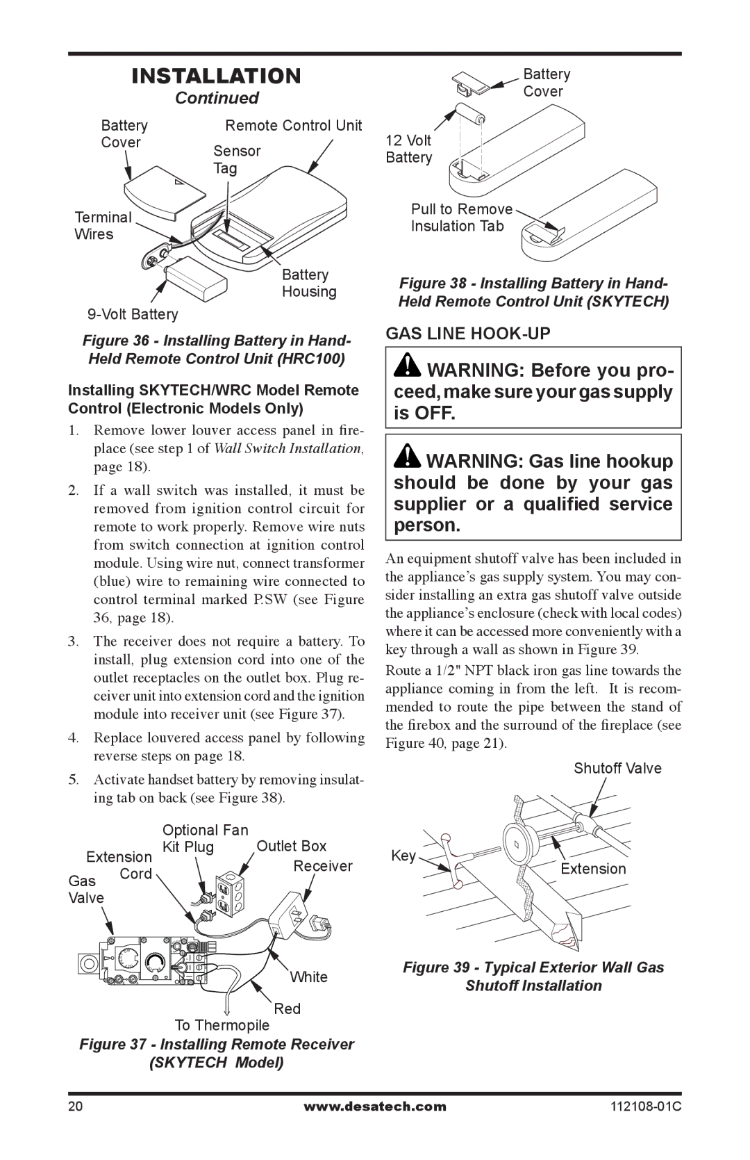
For those seeking convenience, the Desa models are compatible with remote controls and wall-mounted thermostats, allowing users to easily adjust heat settings without leaving the comfort of their couch. This versatility is particularly appealing in colder months when warmth is a priority.
Moreover, the fireplaces come with various media options, such as pebble beds or log sets, enhancing the visual appeal of the flames. The ambiance created by these fireplaces is not only about heat but about creating a cozy atmosphere that draws family and friends together.
In summary, the Desa DVF36TCR, DVF36TCL, and their respective models offer a unique blend of style, efficiency, and safety. With features aimed at enhancing user experience and optimizing home heating, these fireplaces stand out as leading options for those looking to add both warmth and elegance to their living spaces. Whether opting for gas or one of the electric versions, homeowners can trust in the quality and innovation present in the Desa DVF series.

