VENTING INSTALLATION
Installation For Horizontal Termination (Cont.)
13
VENTING INSTALLATION
Continued
3.Attach vent pipe assembly to the fireplace. Set fireplace in front of it’s permanent location to insure minimum clearances. Mark the wall for a 10" square hole (for noncombustible ma- terial such as masonry block or concrete, a 7 1/2" diameter hole is acceptable). See Figure 21. The center of the hole should line up with the
4.Noncombustible Exterior Wall: Apply a bead of
![]() WARNING: Do not recess vent termination in to any wall. This will cause a fire hazard.
WARNING: Do not recess vent termination in to any wall. This will cause a fire hazard.
Combustible Exterior Wall: For vinyl siding, stucco, or wood exteriors, a siding standoff must be installed between the vent cap and exterior wall. The siding standoff prevents excessive heat from damaging siding materials. Siding materials must be cut to accommodate standoff. Bolt the vent cap to the stand- off. Apply
Female
Locking
Lugs
Male
Slots
Rigid Vent Pipe
Figure 20 - Vent Pipe Connections
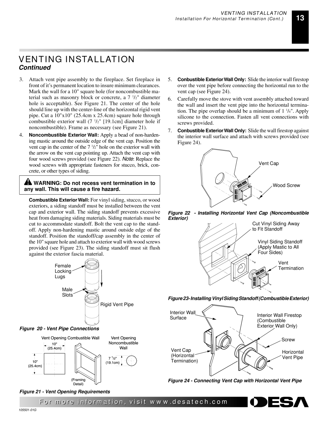
5.Conbustible Exterior Wall Only: Slide the interior wall firestop over the vent pipe before connecting the horizontal run to the vent cap (see Figure 24).
6.Carefully move the stove with vent assembly attached toward the wall and insert the vent pipe into the horizontal termina- tion. The pipe overlap should be a minimum of 1 1/4". Apply silicone to the connection. Fasten all vent connections with screws provided.
7.Conbustible Exterior Wall Only: Slide the wall firestop against the interior wall surface and attach with screws provided (see Figure 24).
Vent Cap
Wood Screw
Figure 22 - Installing Horizontal Vent Cap (Noncombustible Exterior)
Cut Vinyl Siding Away to Fit Standoff
Vinyl Siding Standoff (Apply Mastic to All ![]() Four Sides)
Four Sides)
Vent
![]() Termination
Termination
Figure 23- Installing Vinyl Siding Standoff (Combustible Exterior)
Interior Wall | Interior Wall Firestop | |
Surface | ||
(Combustible | ||
| ||
| Exterior Wall Only) | |
| Screw | |
Vent Cap | Horizontal | |
(Horizontal | ||
Vent Pipe | ||
Termination) | ||
|
Figure 24 - Connecting Vent Cap with Horizontal Vent Pipe
Figure 21 - Vent Opening Requirements
![]() For more
For more![]()
![]()
![]() visit www.
visit www.![]()
![]()
![]() .com
.com![]()
![]()
![]()
![]()
![]()
![]()