CAST IRON STOVE AND
Installing Optional Blower Accessory (Cont.)
Installing Rear Cover
GENERAL VENTING
Location Of Vent Termination
9
CAST IRON STOVE AND DIRECT-VENT BURNER SYSTEM ASSEMBLY
Continued
![]() WARNING: Failure to position the parts in accor- dance with supplied diagrams or failure to use only parts specifically approved with this stove and burner system may result in damage or personal injury.
WARNING: Failure to position the parts in accor- dance with supplied diagrams or failure to use only parts specifically approved with this stove and burner system may result in damage or personal injury.
8.Connect or reconnect gas supply to stove and burner system per Connecting Stove/Burner System to Gas Supply on page 19 of this manual.
![]() WARNING: A qualified service person must con- nect burner system to gas supply. Follow all local codes.
WARNING: A qualified service person must con- nect burner system to gas supply. Follow all local codes.
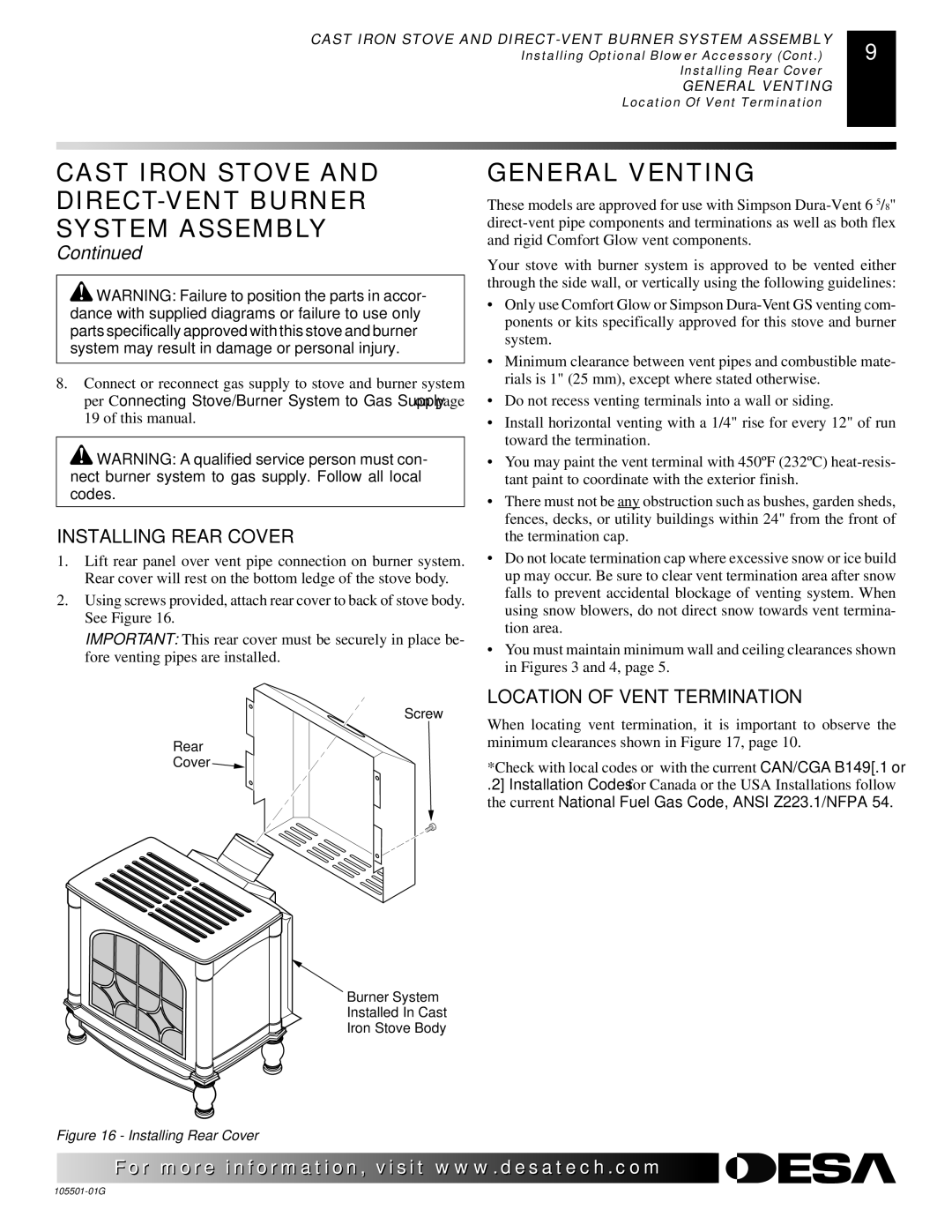
INSTALLING REAR COVER
1.Lift rear panel over vent pipe connection on burner system. Rear cover will rest on the bottom ledge of the stove body.
2.Using screws provided, attach rear cover to back of stove body. See Figure 16.
IMPORTANT: This rear cover must be securely in place be- fore venting pipes are installed.
GENERAL VENTING
These models are approved for use with Simpson
Your stove with burner system is approved to be vented either through the side wall, or vertically using the following guidelines:
•Only use Comfort Glow or Simpson
•Minimum clearance between vent pipes and combustible mate- rials is 1" (25 mm), except where stated otherwise.
•Do not recess venting terminals into a wall or siding.
•Install horizontal venting with a 1/4" rise for every 12" of run toward the termination.
•You may paint the vent terminal with 450ºF (232ºC)
•There must not be any obstruction such as bushes, garden sheds, fences, decks, or utility buildings within 24" from the front of the termination cap.
•Do not locate termination cap where excessive snow or ice build up may occur. Be sure to clear vent termination area after snow falls to prevent accidental blockage of venting system. When using snow blowers, do not direct snow towards vent termina- tion area.
•You must maintain minimum wall and ceiling clearances shown in Figures 3 and 4, page 5.
Rear
Cover ![]()
Figure 16 - Installing Rear Cover
LOCATION OF VENT TERMINATION
Screw
When locating vent termination, it is important to observe the minimum clearances shown in Figure 17, page 10.
*Check with local codes or with the current CAN/CGA B149[.1 or
.2] Installation Codes for Canada or the USA Installations follow the current National Fuel Gas Code, ANSI Z223.1/NFPA 54.
Burner System
Installed In Cast
Iron Stove Body
![]() For more
For more![]()
![]()
![]() visit www.
visit www.![]()
![]()
![]() .com
.com![]()
![]()
![]()
![]()
![]()
![]()