ASSEMBLING SWITCH AND MOUNTING BRACKET
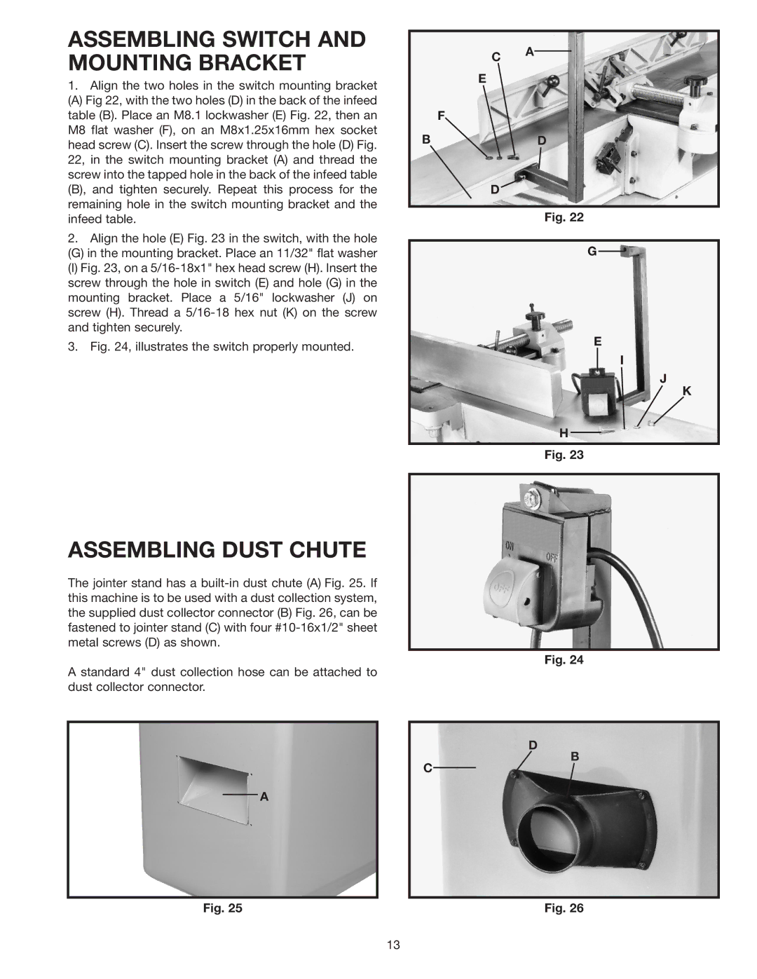
1.Align the two holes in the switch mounting bracket
(A) Fig 22, with the two holes (D) in the back of the infeed table (B). Place an M8.1 lockwasher (E) Fig. 22, then an M8 flat washer (F), on an M8x1.25x16mm hex socket head screw (C). Insert the screw through the hole (D) Fig. 22, in the switch mounting bracket (A) and thread the screw into the tapped hole in the back of the infeed table (B), and tighten securely. Repeat this process for the remaining hole in the switch mounting bracket and the infeed table.
2.Align the hole (E) Fig. 23 in the switch, with the hole
(G) in the mounting bracket. Place an 11/32" flat washer
(I) Fig. 23, on a 5/16-18x1" hex head screw (H). Insert the screw through the hole in switch (E) and hole (G) in the mounting bracket. Place a 5/16" lockwasher (J) on screw (H). Thread a 5/16-18 hex nut (K) on the screw and tighten securely.
3.Fig. 24, illustrates the switch properly mounted.
C A
E
F
BD
D
Fig. 22
G
E
I
J
K
H
Fig. 23
ASSEMBLING DUST CHUTE
The jointer stand has a
A standard 4" dust collection hose can be attached to dust collector connector.
A
Fig. 24
D
B
C
Fig. 25 | Fig. 26 |
13