4. | Rotate flip stop (F) Fig. 54, and tilt the fence outward |
as far as it will go and tighten locking handle (D). Place | |
a square (K) on the table and against the fence to check | |
if the fence is 45 degrees outward to the table. | |
5. | If an adjustment to the positive stop is necessary, |
loosen locking handle (D) Fig. 54, and locknut (M). Rotate | |
adjustment screw (N) until you are certain the fence is 45 | |
degrees outward to the table. Tighten locknut (M). | |
6. | Tilt the fence (G) Fig. 55, inward as far as it will go |
and tighten locking handle (D). Using a square (K) on the | |
M
N
F
D
K
table and against the fence, check if the fence is 45 |
degrees inward to the table. |
7. If an adjustment is necessary, loosen locknut (P) |
Fig. 55. Rotate screw (R) until you are certain the fence |
is 45 degrees inward to the table. Tighten locknut (P) |
and locking handle (D). |
REMOVING, REPLACING, AND RESETTING KNIVES
If the knives are removed from the cutterhead for re- placement or sharpening, care must be used in removing, replacing, and resetting them.
D I S C O N N E C T M A C H I N E F R O M
POWER SOURCE.
1.Move the fence to the rear and remove the cutterhead guard.
![]() BE EXTREMELY CAREFUL THAT YOUR HANDS DO NOT COME IN CONTACT WITH THE KNIVES. THE KNIVES ARE VERY SHARP.
BE EXTREMELY CAREFUL THAT YOUR HANDS DO NOT COME IN CONTACT WITH THE KNIVES. THE KNIVES ARE VERY SHARP.
2.Using wrench (A) Fig. 56, slightly loosen the four locking screws (B) in each knife slot by turning the screws (B) clockwise.
3.Loosen screws (B) Fig. 56, further and remove knife and knife locking bar.
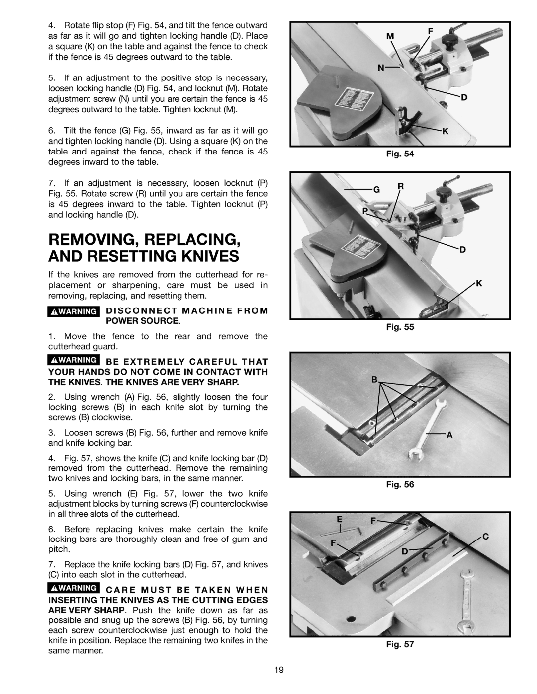
4.Fig. 57, shows the knife (C) and knife locking bar (D) removed from the cutterhead. Remove the remaining two knives and locking bars, in the same manner.
5.Using wrench (E) Fig. 57, lower the two knife adjustment blocks by turning screws (F) counterclockwise in all three slots of the cutterhead.
6.Before replacing knives make certain the knife locking bars are thoroughly clean and free of gum and pitch.
7.Replace the knife locking bars (D) Fig. 57, and knives
(C) into each slot in the cutterhead.
![]() C A R E M U S T B E TA K E N W H E N INSERTING THE KNIVES AS THE CUTTING EDGES ARE VERY SHARP. Push the knife down as far as possible and snug up the screws (B) Fig. 56, by turning each screw counterclockwise just enough to hold the knife in position. Replace the remaining two knifes in the same manner.
C A R E M U S T B E TA K E N W H E N INSERTING THE KNIVES AS THE CUTTING EDGES ARE VERY SHARP. Push the knife down as far as possible and snug up the screws (B) Fig. 56, by turning each screw counterclockwise just enough to hold the knife in position. Replace the remaining two knifes in the same manner.
Fig. 54
G R
P
D
K
Fig. 55
B
A
Fig. 56
E F
C
F
D![]()
Fig. 57
19