FENCE OPERATION
The fence can be moved across the table and can tilt 45 degrees right or left at any position on the table as follows:
NOTE: SWITCH HAS BEEN REMOVED FOR CLARITY OF ILLUSTRATIONS ONLY.
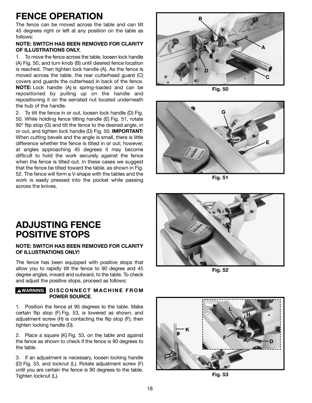
1.To move the fence across the table, loosen lock handle
(A) Fig. 50, and turn knob (B) until desired fence location is reached. Then tighten lock handle (A). As the fence is moved across the table, the rear cutterhead guard (C) covers and guards the cutterhead in back of the fence. NOTE: Lock handle (A) is spring-loaded and can be repositioned by pulling up on the handle and repositioning it on the serrated nut located underneath the hub of the handle.
2.To tilt the fence in or out, loosen lock handle (D) Fig.
50.While holding fence tilting handle (E) Fig. 51, rotate 90° flip stop (G) and tilt the fence to the desired angle, in or out, and tighten lock handle (D) Fig. 50. IMPORTANT: When cutting bevels and the angle is small, there is little difference whether the fence is tilted in or out; however, at angles approaching 45 degrees it may become difficult to hold the work securely against the fence when the fence is tilted out. In these cases we suggest that the fence be tilted toward the table, as shown in Fig.
52.The fence will form a V-shape with the tables and the work is easily pressed into the pocket while passing across the knives.
B
A
D
C
Fig. 50
G
![]() E
E
Fig. 51
ADJUSTING FENCE
POSITIVE STOPS
NOTE: SWITCH HAS BEEN REMOVED FOR CLARITY OF ILLUSTRATIONS ONLY!
The fence has been equipped with positive stops that allow you to rapidly tilt the fence to 90 degree and 45 degree angles, inward and outward, to the table. To check and adjust the positive stops, proceed as follows:
D I S C O N N E C T M A C H I N E F R O M
POWER SOURCE.
1.Position the fence at 90 degrees to the table. Make certain flip stop (F) Fig. 53, is lowered as shown, and adjustment screw (H) is contacting the flip stop (F); then tighten locking handle (D).
2.Place a square (K) Fig. 53, on the table and against the fence as shown to check if the fence is 90 degrees to the table.
3.If an adjustment is necessary, loosen locking handle
(D) Fig. 53, and locknut (L). Rotate adjustment screw (F) until you are certain the fence is 90 degrees to the table. Tighten locknut (L).
Fig. 52
L
H
K
F
D
Fig. 53
18