ADJUSTING TABLE GIBS
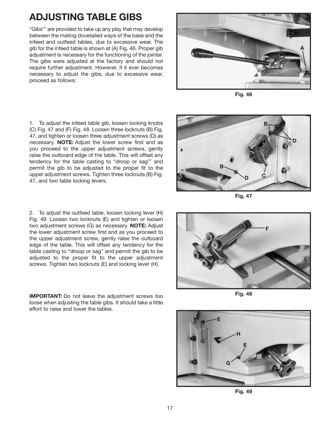
“Gibs”’ are provided to take up any play that may develop between the mating dovetailed ways of the base and the infeed and outfeed tables, due to excessive wear. The gib for the infeed table is shown at (A) Fig. 46. Proper gib adjustment is necessary for the functioning of the jointer. The gibs were adjusted at the factory and should not require further adjustment. However, if it ever becomes necessary to adjust the gibs, due to excessive wear, proceed as follows:
1.To adjust the infeed table gib, loosen locking knobs
(C) Fig. 47 and (F) Fig. 48. Loosen three locknuts (B) Fig. 47, and tighten or loosen three adjustment screws (D) as necessary. NOTE: Adjust the lower screw first and as you proceed to the upper adjustment screws, gently raise the outboard edge of the table. This will offset any tendency for the table casting to “droop or sag”’ and permit the gib to be adjusted to the proper fit to the upper adjustment screws. Tighten three locknuts (B) Fig. 47, and two table locking levers.
2.To adjust the outfeed table, loosen locking lever (H) Fig. 49. Loosen two locknuts (E) and tighten or loosen two adjustment screws (G) as necessary. NOTE: Adjust the lower adjustment screw first and as you proceed to the upper adjustment screw, gently raise the outboard edge of the table. This will offset any tendency for the table casting to “droop or sag” and permit the gib to be adjusted to the proper fit to the upper adjustment screws. Tighten two locknuts (E) and locking lever (H).
IMPORTANT: Do not leave the adjustment screws too loose when adjusting the table gibs. It should take a little effort to raise and lower the tables.
A
Fig. 46
B![]()
D
B![]()
![]() D C
D C
Fig. 47
F
Fig. 48
![]() E
E
H
G
E
G
Fig. 49
17