KNIFE ADJUSTMENTS
In order to do accurate work, the knives must be exactly level with the outfeed table. To check and adjust, proceed as follows:
D I S C O N N E C T M A C H I N E F R O M
POWER SOURCE.
1.Loosen infeed table lock lever and lower infeed table as described under section “INFEED TABLE ADJUSTMENTS”.
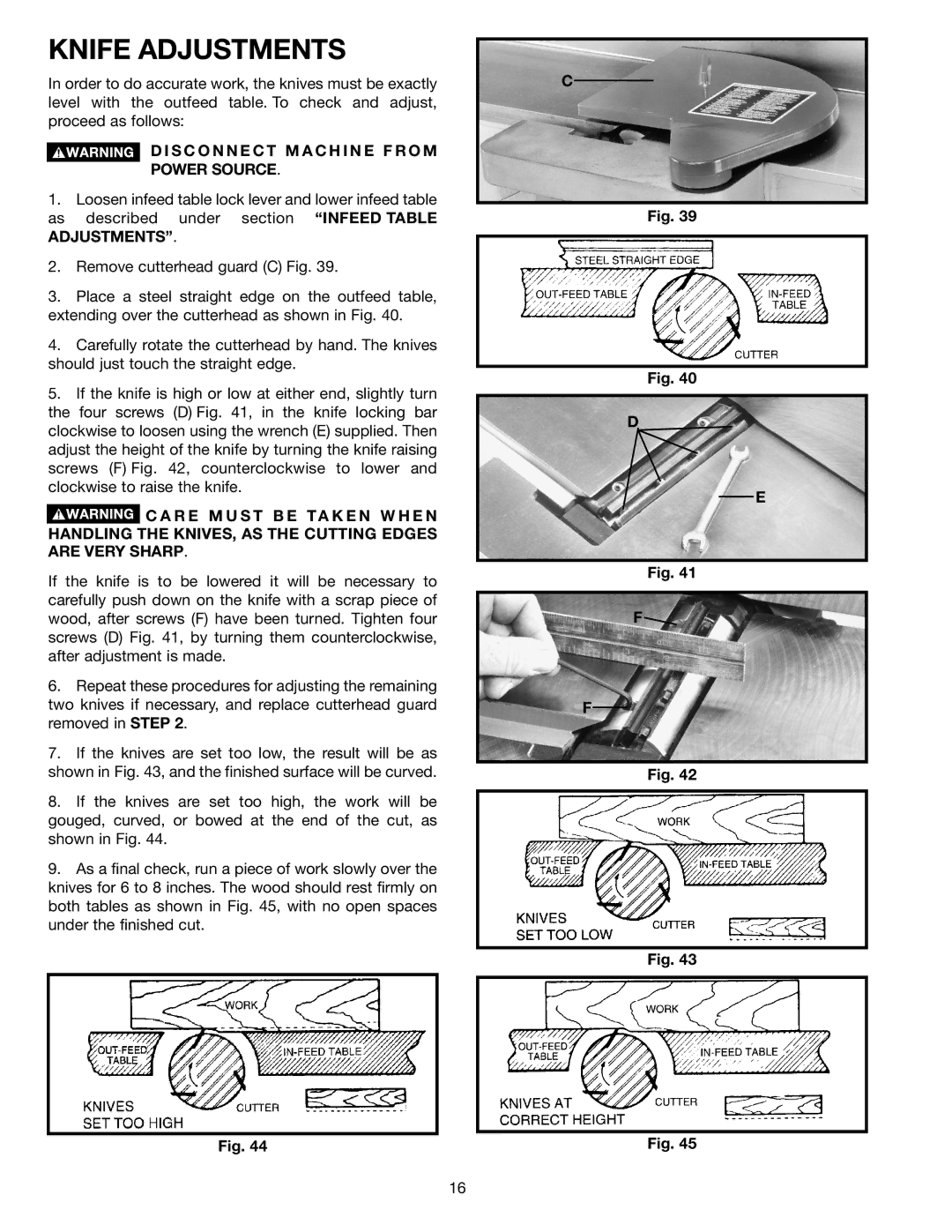
2.Remove cutterhead guard (C) Fig. 39.
3.Place a steel straight edge on the outfeed table, extending over the cutterhead as shown in Fig. 40.
4.Carefully rotate the cutterhead by hand. The knives should just touch the straight edge.
5.If the knife is high or low at either end, slightly turn the four screws (D) Fig. 41, in the knife locking bar clockwise to loosen using the wrench (E) supplied. Then adjust the height of the knife by turning the knife raising screws (F) Fig. 42, counterclockwise to lower and clockwise to raise the knife.
![]() C A R E M U S T B E T A K E N W H E N HANDLING THE KNIVES, AS THE CUTTING EDGES ARE VERY SHARP.
C A R E M U S T B E T A K E N W H E N HANDLING THE KNIVES, AS THE CUTTING EDGES ARE VERY SHARP.
If the knife is to be lowered it will be necessary to carefully push down on the knife with a scrap piece of wood, after screws (F) have been turned. Tighten four screws (D) Fig. 41, by turning them counterclockwise, after adjustment is made.
6.Repeat these procedures for adjusting the remaining two knives if necessary, and replace cutterhead guard removed in STEP 2.
7.If the knives are set too low, the result will be as shown in Fig. 43, and the finished surface will be curved.
8.If the knives are set too high, the work will be gouged, curved, or bowed at the end of the cut, as shown in Fig. 44.
9.As a final check, run a piece of work slowly over the knives for 6 to 8 inches. The wood should rest firmly on both tables as shown in Fig. 45, with no open spaces under the finished cut.
Fig. 44
C
Fig. 39
Fig. 40
D
E
Fig. 41
F![]()
F
Fig. 42
Fig. 43
Fig. 45
16