OPERATING CONTROLS AND ADJUSTMENTS
STARTING AND STOPPING JOINTER
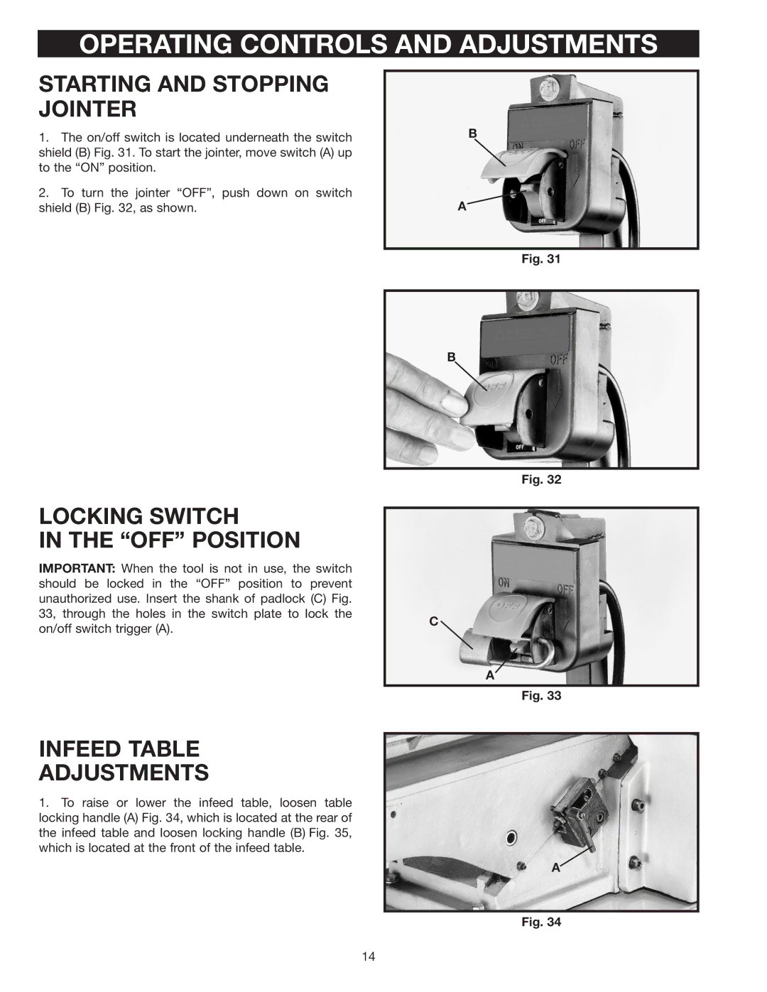
1.The on/off switch is located underneath the switch shield (B) Fig. 31. To start the jointer, move switch (A) up to the “ON” position.
2.To turn the jointer “OFF”, push down on switch shield (B) Fig. 32, as shown.
B
A
Fig. 31
B
Fig. 32
LOCKING SWITCH
IN THE “OFF” POSITION
IMPORTANT: When the tool is not in use, the switch should be locked in the “OFF” position to prevent unauthorized use. Insert the shank of padlock (C) Fig. 33, through the holes in the switch plate to lock the on/off switch trigger (A).
C ![]()
A
Fig. 33
INFEED TABLE
ADJUSTMENTS
1.To raise or lower the infeed table, loosen table locking handle (A) Fig. 34, which is located at the rear of the infeed table and loosen locking handle (B) Fig. 35, which is located at the front of the infeed table.
A
Fig. 34
14
