2.Remove the four bolts that attach the motor (A) Fig.
5to top of the stand. NOTE: SAVE THESE BOLTS AS
THEY WILL BE USED TO ATTACH THE MOTOR TO THE MOUNTING BRACKETS.
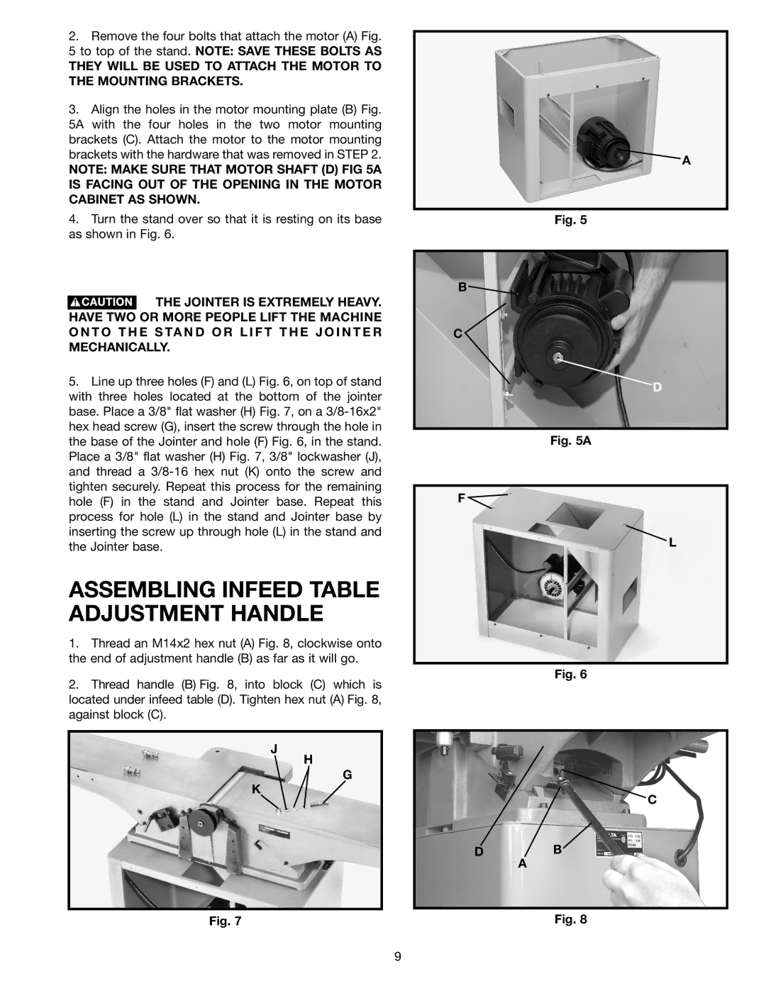
3.Align the holes in the motor mounting plate (B) Fig.
5A with the four holes in the two motor mounting brackets (C). Attach the motor to the motor mounting brackets with the hardware that was removed in STEP 2.
NOTE: MAKE SURE THAT MOTOR SHAFT (D) FIG 5A IS FACING OUT OF THE OPENING IN THE MOTOR CABINET AS SHOWN.
4.Turn the stand over so that it is resting on its base as shown in Fig. 6.
![]() THE JOINTER IS EXTREMELY HEAVY. HAVE TWO OR MORE PEOPLE LIFT THE MACHINE O N T O T H E S TA N D O R L I F T T H E J O I N T E R MECHANICALLY.
THE JOINTER IS EXTREMELY HEAVY. HAVE TWO OR MORE PEOPLE LIFT THE MACHINE O N T O T H E S TA N D O R L I F T T H E J O I N T E R MECHANICALLY.
5.Line up three holes (F) and (L) Fig. 6, on top of stand with three holes located at the bottom of the jointer base. Place a 3/8" flat washer (H) Fig. 7, on a
ASSEMBLING INFEED TABLE ADJUSTMENT HANDLE
1.Thread an M14x2 hex nut (A) Fig. 8, clockwise onto the end of adjustment handle (B) as far as it will go.
2.Thread handle (B) Fig. 8, into block (C) which is located under infeed table (D). Tighten hex nut (A) Fig. 8, against block (C).
J
H
G
K
Fig. 7
A
Fig. 5
B ![]()
C
D
Fig. 5A
F ![]()
L
Fig. 6
C
DB
A
Fig. 8
9