Once made, these adjustments should remain accurate. Take a little time now to follow | After confirming that those elements are aligned, proceed with alignment of the blade to the | |||||||
these directions carefully to maintain the accuracy of which your saw is capable. |
| fence using the following procedure: | ||||||
RAIL LOCK ADJUSTMENT |
|
|
|
|
| 1. Unlock the rail lock lever (W) and locate the two fence locator screws (AA) that support | ||
|
|
| FIG. 18 |
| the fence on the front and rear rails. | |||
(Tightening Fence Clamping System) |
|
| ||||||
|
|
| 2. Loosen the rear locator screw and adjust the position of the fence in the groove on the | |||||
1. Lock the rail lock lever (W). |
|
|
|
| ||||
|
|
|
| fence until it sets the fence face parallel to the blade. Make sure you measure from the | ||||
2. On the underside of the saw, loosen the nut (LL) (Fig. 18). |
| |||||||
| fence face to the front and back of the blade to ensure alignment. | |||||||
3. Tighten the hex rod (MM) until the spring on the locking system |
| |||||||
| 3. Tighten the locator screw and repeat on the left side of the blade. | |||||||
is compressed creating the desired tension on the rail lock lever. | MM | |||||||
4. Check rip scale adjustment. | ||||||||
Retighten the jam nut against the hex rod. |
| |||||||
|
| BEVEL STOP AND POINTER ADJUSTMENT | ||||||
4. Flip the saw over and check that the fence does not move when | LL | |||||||
(Calibrating Bevel Scale) | ||||||||
the lock lever is engaged. If the fence is still loose, tighten the |
| |||||||
| Calibrating the bevel system on the saw may require two separate steps, one for the bevel | |||||||
spring further. |
|
|
|
|
| |||
RIP SCALE ADJUSTMENT |
|
|
| FIG. 19 |
| scale and another for the bevel pointer. The scale should always be checked first followed | ||
|
|
|
| by adjustments to the red pointer. | ||||
(Calibrating Rip Scale) |
|
|
|
|
| |||
|
|
|
|
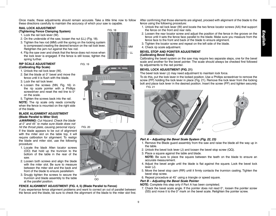
| BEVEL LOCK ADJUSTMENT (FIG. 21) | |||
1. Unlock the rail lock lever (W). |
|
|
|
| ||||
|
|
|
| The bevel lock lever (J) may need adjustment to maintain lock force. | ||||
2. Set the blade at 0° bevel and move the |
|
| ||||||
|
| To do this, put the lock lever in the locked position. Use a Phillips screwdriver to remove the | ||||||
fence until it is flush with the blade. |
|
|
| |||||
|
|
| screw (PP) holding the lock lever in place (Fig. 21). Remove the lock lever from the locking | |||||
3. Lock the rail lock lever. |
|
|
|
|
| |||
|
|
|
|
| bolt and place lock lever in the desired position. Insert the screw (PP) and tighten securely. | |||
4. Loosen the screws (NN, Fig. 16) | in |
|
| |||||
|
| FIG. 21 | ||||||
the rip scale pointer with a Phillips |
|
| ||||||
|
|
| ||||||
screwdriver and reset the red line to 0° |
|
| J | |||||
on the scale. |
|
|
|
|
| |||
|
|
|
|
|
| |||
5. Tighten the screws back into the rail. |
| W |
|
| ||||
NOTE: The rip scale only reads correctly |
|
|
| |||||
when the fence is mounted on the right side |
|
|
| |||||
of the blade. |
|
|
|
|
|
|
| |
BLADE ALIGNMENT ADJUSTMENT |
|
|
|
| ||||
(Blade Parallel to Miter Slot) |
|
|
|
|
| |||
WARNING: Cut Hazard. Check the blade |
|
| J | |||||
at 0˚ and 45˚ to make sure blade does not |
|
| ||||||
|
|
| ||||||
hit the throat plate, causing personal injury. | FIG. 20 |
| PP | |||||
If the blade appears to be out of alignment |
|
| ||||||
|
|
| ||||||
with the miter slot on the table top, it will |
|
|
| |||||
require calibration for alignment. To | realign |
|
| Part A – Adjusting the Bevel Scale System (Fig. 22, 23) | ||||
the blade and miter slot, use the following |
|
| ||||||
|
| 1. Remove the Blade guard assembly from the saw and raise the blade all the way up in | ||||||
procedure: |
|
|
|
|
|
| ||
|
|
|
|
|
| the table. | ||
1. Locate the | black Allen | locator | screws |
|
| |||
|
| 2. Unlock the bevel lock lever (J) and loosen the bevel stop screw (QQ). | ||||||
(OO) that | hold up the | trunnion | to | the |
|
| ||
|
| 3. Place a square against the table and blade. | ||||||
bottom of the table in the rear of the |
|
| ||||||
|
| NOTE: Be sure to place the square between the teeth on the blade to ensure an | ||||||
saw. |
|
|
|
|
|
| ||
2. Loosen both screws and align the blade |
|
| accurate measurement. | |||||
|
| 4. Adjust the bevel angle until the blade is flat against the square. Lock the bevel lock | ||||||
with the miter slot. Be sure to measure |
|
| ||||||
between the miter slot and the back and |
|
| lever (J). | |||||
front of the blade to ensure parallelism. |
|
| 5. Move the bevel stop cam (RR) until it firmly contacts the trunnion casting. Tighten the | |||||
3. Snugly tighten the screws to secure the |
|
| bevel stop screw. | |||||
|
| 6. Repeat procedure at 45˚ using a triangle or speed square. | ||||||
trunnion and blade assembly to the table | OO |
| ||||||
at the parallel position. |
|
|
|
| Part B – Adjusting the Bevel Scale Pointer | |||
|
|
|
|
| ||||
FENCE ALIGNMENT ADJUSTMENT (FIG. 4, 5) (Blade Parallel to Fence) | NOTE: Complete this step only if Part A has been completed. | |
7. Check the bevel scale angle. If the pointer does not read 0°, loosen the pointer screw | ||
If you experience fence alignment problems and want to correct an out of parallel between | ||
(SS) and move it to the 0° mark on the bevel scale. Retighten the pointer screw. | ||
the fence and the blade, be sure to check the alignment of the blade to the miter slot first. | ||
|
English
9