•Installation
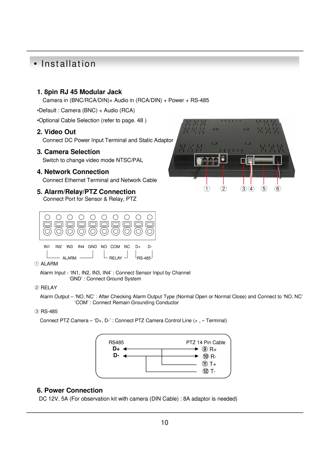
1.8pin RJ 45 Modular Jack
Camera in (BNC/RCA/DIN)+ Audio in (RCA/DIN) + Power +
•Optional Cable Selection (refer to page. 48 )
2. | Video Out |
|
|
|
|
|
|
|
|
| Connect DC Power Input Terminal and Static Adaptor |
|
|
|
|
|
|
|
|
3. | Camera Selection |
|
|
|
|
|
|
|
|
| Switch to change video mode NTSC/PAL |
|
|
|
|
|
|
|
|
4. | Network Connection |
|
|
|
|
|
|
|
|
| Connect Ethernet Terminal and Network Cable |
|
|
|
|
|
|
|
|
5. | Alarm/Relay/PTZ Connection | ① ② | ③ ④ ⑤ ⑥ | ||||||
|
|
|
|
|
|
|
| ||
Connect Port for Sensor & Relay, PTZ
IN1 IN2 IN3 IN4 GND NO COM NC D+ D-
ALARM
①ALARM
![]() RELAY
RELAY ![]()
![]() RS-485
RS-485![]()
Alarm Input - ‘IN1, IN2, IN3, IN4’ : Connect Sensor Input by Channel ‘GND’ : Connect Ground System
②RELAY
Alarm Output – ‘NO, NC’ : After Checking Alarm Output Type (Normal Open or Normal Close) and Connect to ‘NO, NC’ ‘COM’ : Connect Remain Grounding Conductor
③
Connect PTZ Camera – ‘D+,
RS485 | PTZ 14 Pin Cable |
D+ | ⑨ R+ |
D- | ⑩ R- |
| ⑪ T+ |
| ⑫ T- |
6. Power Connection
DC 12V, 5A (For observation kit with camera (DIN Cable) : 8A adaptor is needed)
10