®
DIGITAL CONTROL INCORPORATED
Receiver
Handle | Speaker | Trigger | Display |
| |||
Temperature |
|
| Windows |
|
|
| |
& Distance |
|
|
|
Conversion |
|
|
|
Chart |
|
|
|
Battery |
|
| Depth/Locating |
Compartment |
|
| Antenna Screws |
Back Panel ![]()
Front Panel
Pitch/Roll
Antenna Screws
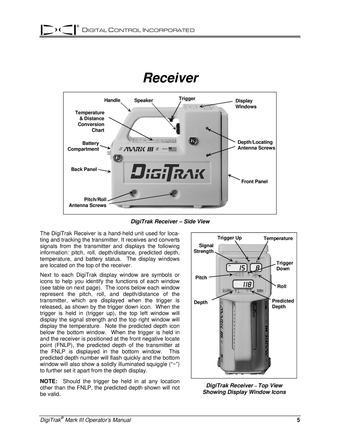
DigiTrak Receiver – Side View
The DigiTrak Receiver is a
Next to each DigiTrak display window are symbols or icons to help you identify the functions of each window (see table on next page). The icons below each window represent the pitch, roll, and depth/distance of the transmitter, which are displayed when the trigger is released, as shown by the trigger down icon. When the trigger is held in (trigger up), the top left window will display the signal strength and the top right window will display the temperature. Note the predicted depth icon below the bottom window. When the trigger is held in and the receiver is positioned at the front negative locate point (FNLP), the predicted depth of the transmitter at the FNLP is displayed in the bottom window. This predicted depth number will flash quickly and the bottom window will also show a solidly illuminated squiggle (“~”) to further set it apart from the depth display.
Trigger Up | Temperature | |
Signal |
|
|
Strength |
|
|
~ | I5 | Trigger |
Down | ||
|
| |
Pitch | I I8 |
|
| Roll | |
Depth |
| Predicted |
|
| Depth |
NOTE: Should the trigger be held in at any location | DigiTrak Receiver – Top View | |
other than the FNLP, the predicted depth shown will not | ||
Showing Display Window Icons | ||
be valid. |
DigiTrak® Mark III Operator’s Manual | 5 |
