® | Remote Display |
|
Remote Steering
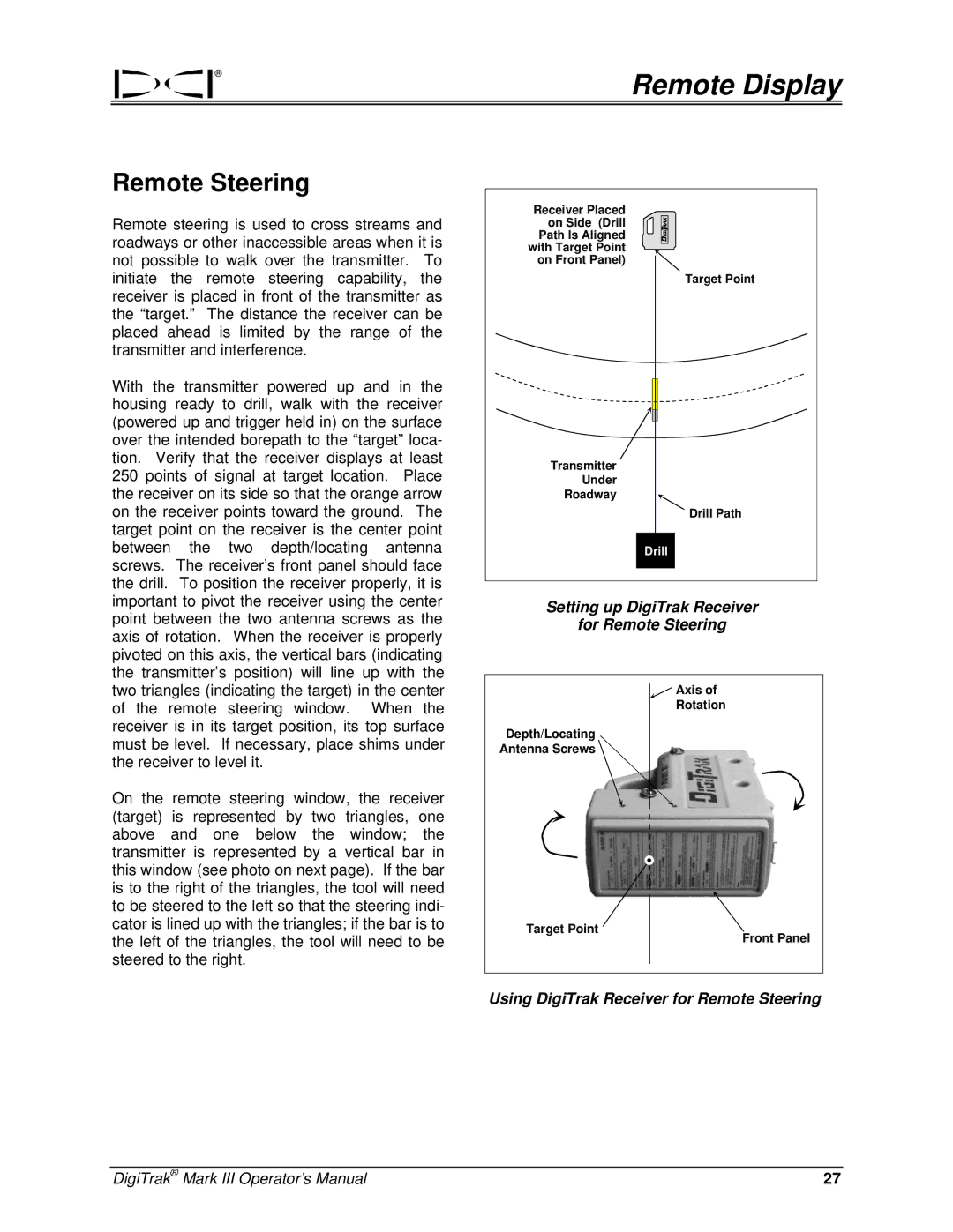
Remote steering is used to cross streams and roadways or other inaccessible areas when it is not possible to walk over the transmitter. To initiate the remote steering capability, the receiver is placed in front of the transmitter as the “target.” The distance the receiver can be placed ahead is limited by the range of the transmitter and interference.
With the transmitter powered up and in the housing ready to drill, walk with the receiver (powered up and trigger held in) on the surface over the intended borepath to the “target” loca- tion. Verify that the receiver displays at least 250 points of signal at target location. Place the receiver on its side so that the orange arrow on the receiver points toward the ground. The target point on the receiver is the center point between the two depth/locating antenna screws. The receiver’s front panel should face the drill. To position the receiver properly, it is important to pivot the receiver using the center point between the two antenna screws as the axis of rotation. When the receiver is properly pivoted on this axis, the vertical bars (indicating the transmitter’s position) will line up with the two triangles (indicating the target) in the center of the remote steering window. When the receiver is in its target position, its top surface must be level. If necessary, place shims under the receiver to level it.
On the remote steering window, the receiver (target) is represented by two triangles, one above and one below the window; the transmitter is represented by a vertical bar in this window (see photo on next page). If the bar is to the right of the triangles, the tool will need to be steered to the left so that the steering indi- cator is lined up with the triangles; if the bar is to the left of the triangles, the tool will need to be steered to the right.
Receiver Placed
on Side (Drill Path Is Aligned
with Target Point on Front Panel)
Target Point
Transmitter
Under
Roadway
Drill Path
Drill
Setting up DigiTrak Receiver
for Remote Steering
![]() Axis of
Axis of
Rotation
Depth/Locating
Antenna Screws
Target Point
Front Panel
Using DigiTrak Receiver for Remote Steering
DigiTrak® Mark III Operator’s Manual | 27 |
