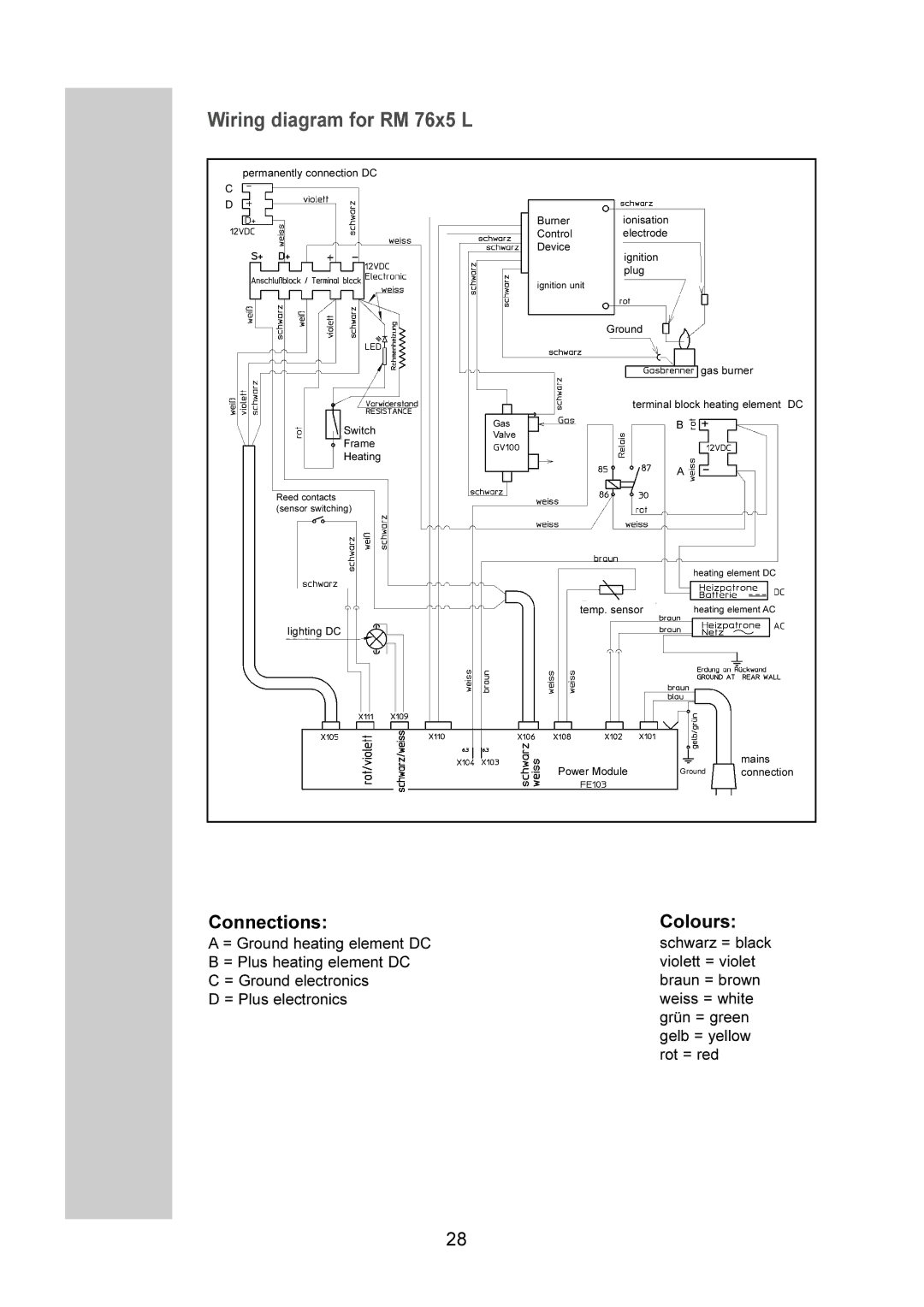
Wiring diagram for RM 76x5 L
permanently connection DC
C
D
Switch
Frame
Heating
Reed contacts (sensor switching)
lighting DC
|
| Burner |
| ionisation |
|
|
| ||||||
|
| Control |
| electrode |
|
|
| ||||||
|
| Device |
|
|
|
|
|
|
|
|
|
|
|
|
|
|
| ignition |
|
|
| ||||||
|
|
|
| plug |
|
|
| ||||||
|
| ignition unit |
|
|
|
|
|
|
|
|
|
|
|
|
|
|
|
|
|
|
|
|
|
| |||
|
|
|
|
|
|
|
|
|
| ||||
|
|
| Ground |
|
|
|
|
| |||||
|
|
|
|
|
|
|
|
|
|
|
|
| |
|
|
|
|
|
|
|
|
|
|
|
| gas burner |
|
|
|
|
|
|
|
|
|
|
|
|
|
|
|
|
|
|
|
| terminal block heating element DC | ||||||||
|
|
|
|
|
|
|
|
|
|
|
| ||
Gas |
|
|
|
| B |
|
|
| |||||
Valve |
|
|
|
|
|
|
|
|
|
|
|
| |
|
|
|
|
|
|
|
|
|
|
|
|
|
|
|
|
|
|
|
|
| A | ||||||
|
| heating element DC |
|
|
|
temp. sensor |
|
|
| heating element AC |
|
|
|
| mains |
Power Module |
| Ground |
| connection |
|
|
|
|
|
|
|
|
|
|
Connections:Colours:
A = Ground heating element DC B = Plus heating element DC C = Ground electronics
D = Plus electronics
schwarz = black violett = violet braun = brown weiss = white grün = green gelb = yellow rot = red
28
