INSTALLATION
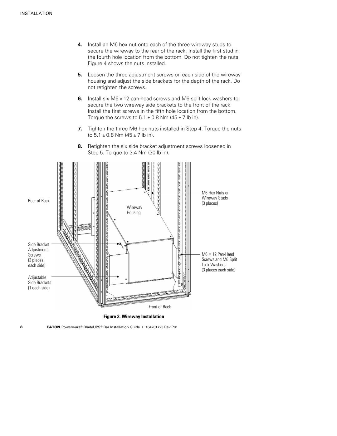
Rear of Rack
Side Bracket Adjustment Screws
(3 places each side)
Adjustable Side Brackets (1 each side)
4.Install an M6 hex nut onto each of the three wireway studs to secure the wireway to the rear of the rack. Install the first stud in the fourth hole location from the bottom. Do not tighten the nuts. Figure 4 shows the nuts installed.
5.Loosen the three adjustment screws on each side of the wireway housing and adjust the side brackets for the depth of the rack. Do not retighten the screws.
6.Install six M6×12
7.Tighten the three M6 hex nuts installed in Step 4. Torque the nuts to 5.1 ± 0.8 Nm (45 ± 7 lb in).
8.Retighten the six side bracket adjustment screws loosened in Step 5. Torque to 3.4 Nm (30 lb in).
M6 Hex Nuts on Wireway Studs
(3 places)
Wireway
Housing
![]() M6×12
M6×12
(3 places each side)
Front of Rack
Figure 3. Wireway Installation
8 | EATON Powerware® BladeUPS® Bar Installation Guide S 164201723 Rev P01 |