INSTALLATION
Installation
To install the BladeUPS Bar 60:
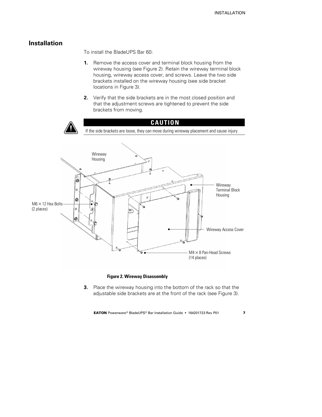
1.Remove the access cover and terminal block housing from the wireway housing (see Figure 2). Retain the wireway terminal block housing, wireway access cover, and screws. Leave the two side brackets installed on the wireway housing (see side bracket locations in Figure 3).
2.Verify that the side brackets are in the most closed position and that the adjustment screws are tightened to prevent the side brackets from moving.
C A U T I O N
If the side brackets are loose, they can move during wireway placement and cause injury.
Wireway
Housing
Wireway
Terminal Block
Housing
M6×12 Hex Bolts (2 places)
Wireway Access Cover
M4×8
(14 places)
Figure 2. Wireway Disassembly
3.Place the wireway housing into the bottom of the rack so that the adjustable side brackets are at the front of the rack (see Figure 3).
EATON Powerware® BladeUPS® Bar Installation Guide S 164201723 Rev P01 | 7 |