INSTALLATION
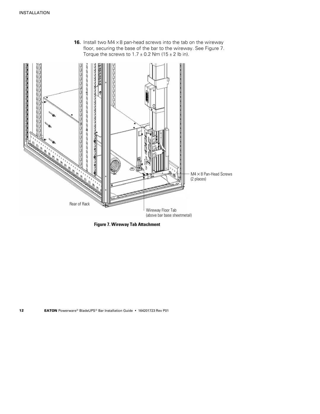
16.Install two M4×8
Rear of Rack
M4×8
Wireway Floor Tab
(above bar base sheetmetal)
Figure 7. Wireway Tab Attachment
12 | EATON Powerware® BladeUPS® Bar Installation Guide S 164201723 Rev P01 |
INSTALLATION
16.Install two M4×8
Rear of Rack
M4×8
Wireway Floor Tab
(above bar base sheetmetal)
12 | EATON Powerware® BladeUPS® Bar Installation Guide S 164201723 Rev P01 |