INSTALLATION
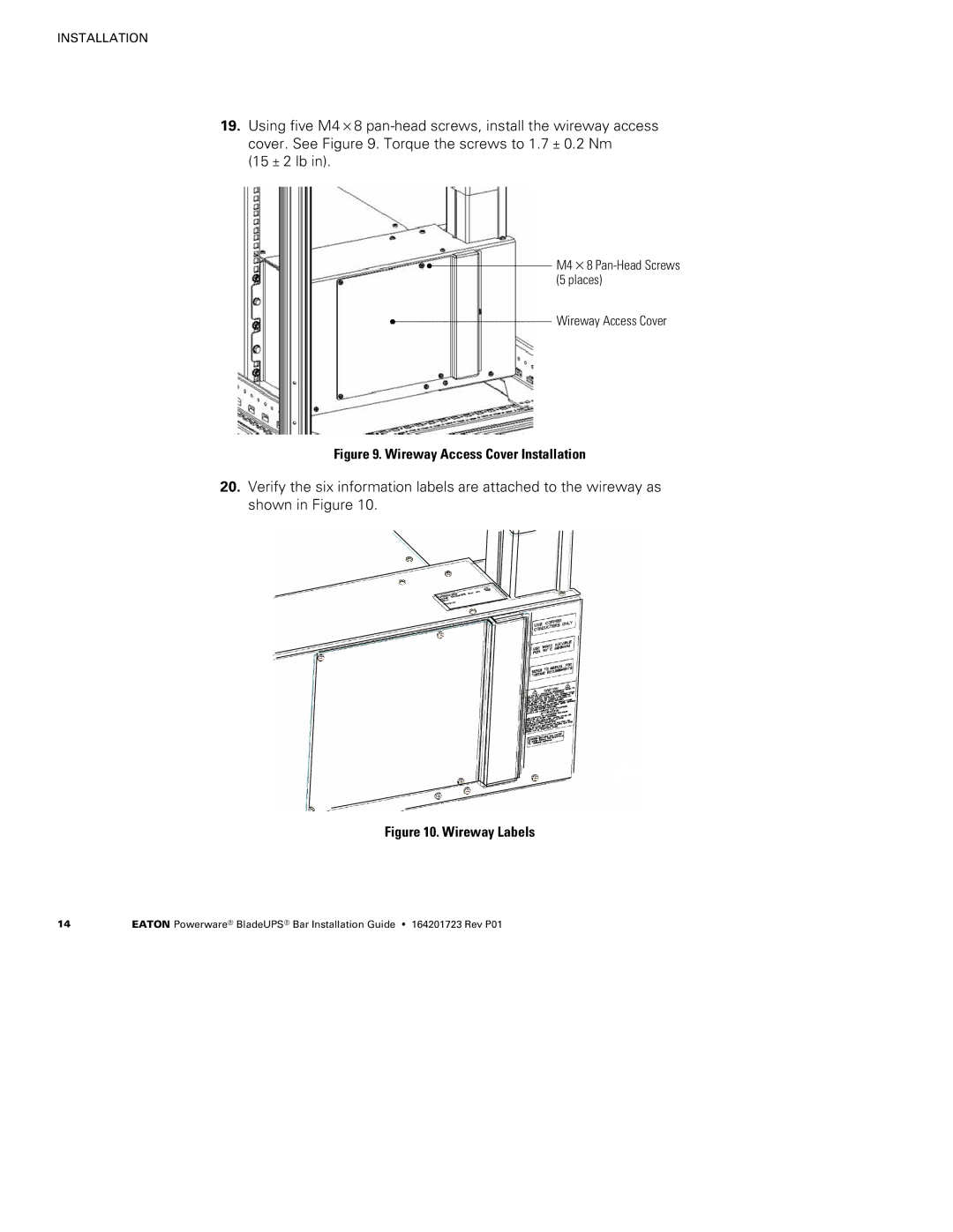
19.Using five M4×8
(15 ± 2 lb in).
M4×8
Wireway Access Cover
Figure 9. Wireway Access Cover Installation
20.Verify the six information labels are attached to the wireway as shown in Figure 10.
Figure 10. Wireway Labels
14 | EATON Powerware® BladeUPS® Bar Installation Guide S 164201723 Rev P01 |
