INSTALLATION
NOTE Verify that the bar is secure as shown in Figure 4. The sheetmetal at the base of the bar should be below the tab on the wireway floor.
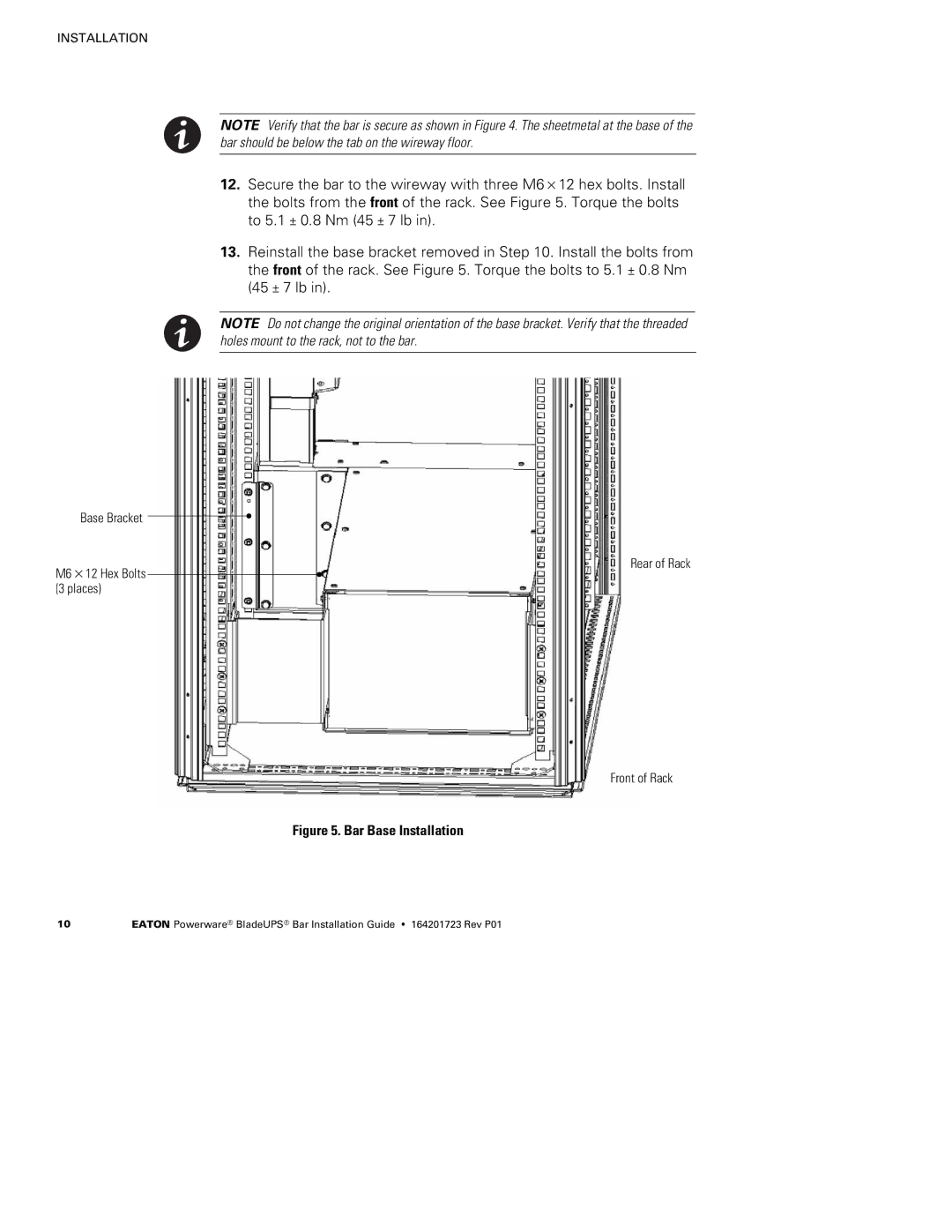
12.Secure the bar to the wireway with three M6×12 hex bolts. Install the bolts from the front of the rack. See Figure 5. Torque the bolts to 5.1 ± 0.8 Nm (45 ± 7 lb in).
13.Reinstall the base bracket removed in Step 10. Install the bolts from the front of the rack. See Figure 5. Torque the bolts to 5.1 ± 0.8 Nm (45 ± 7 lb in).
NOTE Do not change the original orientation of the base bracket. Verify that the threaded holes mount to the rack, not to the bar.
Base Bracket
M6×12 Hex Bolts (3 places)
Rear of Rack
Front of Rack
Figure 5. Bar Base Installation
10 | EATON Powerware® BladeUPS® Bar Installation Guide S 164201723 Rev P01 |