INSTALLATION
14.Secure the base bracket to the rack with three M6×12 hex bolts. Install the bolts from the rear of the rack.
Use a large screwdriver or crowbar to lift the bar in place to align the holes in the base bracket with the holes in the rack.
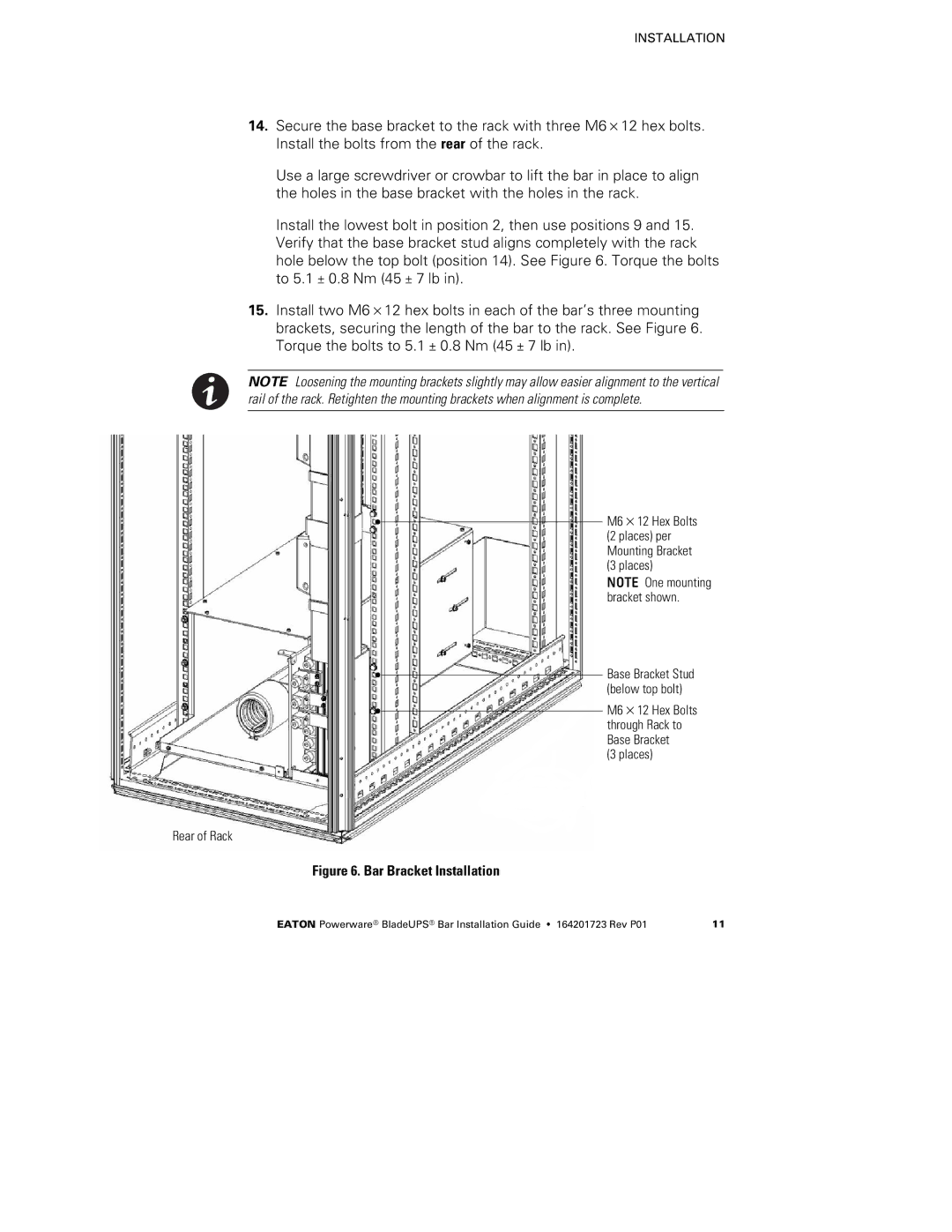
Install the lowest bolt in position 2, then use positions 9 and 15. Verify that the base bracket stud aligns completely with the rack hole below the top bolt (position 14). See Figure 6. Torque the bolts to 5.1 ± 0.8 Nm (45 ± 7 lb in).
15.Install two M6×12 hex bolts in each of the bar’s three mounting brackets, securing the length of the bar to the rack. See Figure 6. Torque the bolts to 5.1 ± 0.8 Nm (45 ± 7 lb in).
NOTE Loosening the mounting brackets slightly may allow easier alignment to the vertical rail of the rack. Retighten the mounting brackets when alignment is complete.
M6×12 Hex Bolts (2 places) per Mounting Bracket (3 places)
NOTE One mounting bracket shown.
Base Bracket Stud (below top bolt)
M6×12 Hex Bolts through Rack to Base Bracket
(3 places)
Rear of Rack
Figure 6. Bar Bracket Installation
EATON Powerware® BladeUPS® Bar Installation Guide S 164201723 Rev P01 | 11 |