INSTALLATION
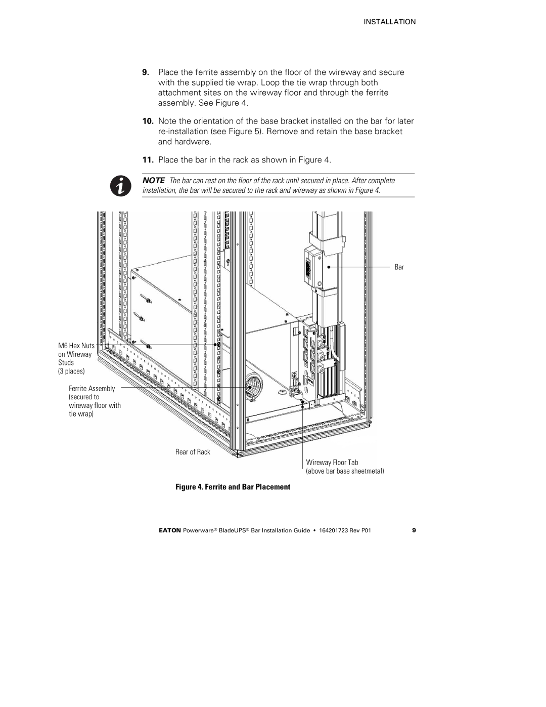
9.Place the ferrite assembly on the floor of the wireway and secure with the supplied tie wrap. Loop the tie wrap through both attachment sites on the wireway floor and through the ferrite assembly. See Figure 4.
10.Note the orientation of the base bracket installed on the bar for later
11.Place the bar in the rack as shown in Figure 4.
NOTE The bar can rest on the floor of the rack until secured in place. After complete installation, the bar will be secured to the rack and wireway as shown in Figure 4.
M6 Hex Nuts on Wireway Studs
(3 places)
Ferrite Assembly (secured to wireway floor with tie wrap)
Rear of Rack
Figure 4. Ferrite and Bar Placement
Bar
Wireway Floor Tab
(above bar base sheetmetal)
EATON Powerware® BladeUPS® Bar Installation Guide S 164201723 Rev P01 | 9 |