USING THE DIRECT OUTPUTS
The DIRECT OUTPUTS provide an unbalanced line- level signal from each of the 8 Input channels. This signal comes from the output of the preamplifier stage on each input channel, prior to the A/D converter and subsequent digital signal processing.
Use the DIRECT OUTPUTS to connect a continuous music source (e.g., satellite feed, prerecorded background music, or
USING OUTPUTS A THROUGH J
These outputs provide a balanced
USING THE RECORD OUTPUT
The A and B output signals are provided at the RECORD output jacks, which are industry standard unbalanced RCA connectors. Connect these to the Tape Input jacks on a tape deck or other recording device to record the mix at the A and B outputs.
USING THE REMOTE CONTROLS
Connect one or up to nine remote controls to the REMOTE BUS connection. Each remote control has an
There are two remote control versions available:
DX-SW4 Selection Remote (4-Button/4-LED)
This remote device is designed to select functions such as preset selection, mute, and
Refer to Appendix C for a list of the predefined functions available for the Selection Remote Control. Refer to "Remotes" on page 21 for instructions on custom programming the
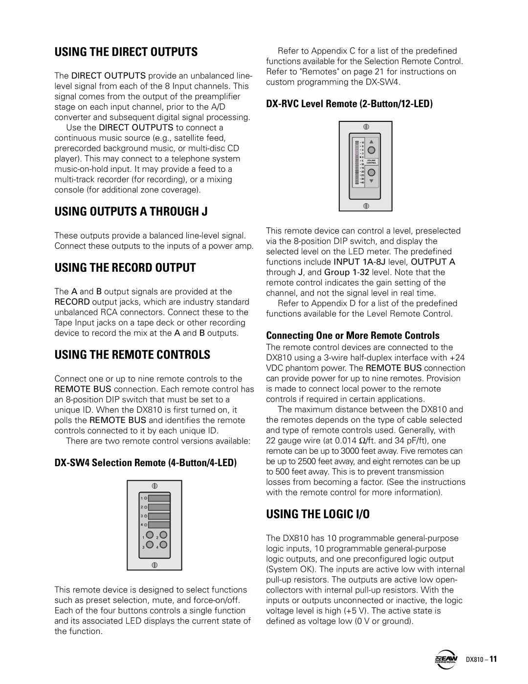
DX-RVC Level Remote (2-Button/12-LED)
This remote device can control a level, preselected via the
Refer to Appendix D for a list of the predefined functions available for the Level Remote Control.
Connecting One or More Remote Controls
The remote control devices are connected to the DX810 using a
The maximum distance between the DX810 and the remotes depends on the type of cable selected and type of remote controls used. Generally, with 22 gauge wire (at 0.014 Ω/ft. and 34 pF/ft), one remote can be up to 3000 feet away. Five remotes can be up to 2500 feet away, and eight remotes can be up to 500 feet away. This is to prevent transmission losses from becoming a factor. (See the instructions with the remote control for more information).
USING THE LOGIC I/O
The DX810 has 10 programmable
DX810 – 11