LIGHTING INSTRUCTIONS
1.Main Electrical power supply must always be switched on to the unit with the two burner switches in the off position (up) before lighting the heater.
2.Turn on main gas supply.
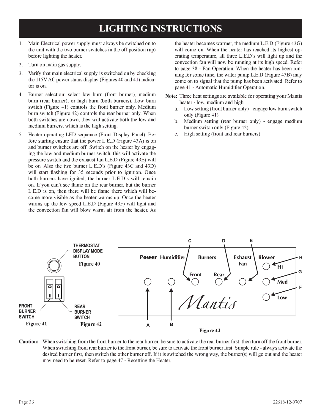
3.Verify that main electrical supply is switched on by checking the 115V AC power status display (Figures 40 and 41) indica- tor is on.
4.Burner selection: select low burn (front burner), medium burn (rear burner), or high burn (both burners). Low burn switch (Figure 41) controls the front burner only. Medium burn switch (Figure 42) controls the rear burner only. When both switches are down, they will activate both the low and medium burners, which is the high setting.
5.Heater operating LED sequence (Front Display Panel). Be- fore starting ensure that the power L.E.D (Figure 43A) is on and burner switches are off. Switch on the heater by engag- ing the low and medium burner switch, this will activate the pressure switch and the exhaust fan L.E.D (Figure 43E) will be on. Also the two burner L.E.D’s (Figure 43C and 43D) will start flashing for 35 seconds prior to ignition. Once both burners have ignited, the burner L.E.D’s will remain on. If you can’t see flame on the rear burner, but the burner L.E.D is on, then there will be flame there which will be- come more visible as the heater warms up. Once the heater warms up the low speed L.E.D (Figure 43F) will light and the convection fan will blow warm air from the heater. As
the heater becomes warmer, the medium L.E.D (Figure 43G) will come on. When the heater has reached its highest op- erating temperature, all three L.E.D’s will light up and the convection fan will now be running at its high speed. Refer to page 38 - Fan Operation. When the heater has been run- ning for some time, the water pump L.E.D (Figure 43B) may come on to signal that the pump has been activated. Refer to page 41 - Automatic Humidifier Operation.
Note: Three heat settings are available for operating your Mantis heater - low, medium and high.
a.Low setting (front burner only) - engage low burn switch only (Figure 41)
b.Medium setting (rear burner only) - engage medium burner switch only (Figure 42)
c.High setting (front and rear burners).
| THERMOSTAT |
| C | D | E |
|
|
|
|
| |
| DISPLAY MODE |
|
|
|
|
| BUTTON |
|
|
| H |
| Figure 40 |
|
|
|
|
|
|
|
|
| G |
|
|
|
|
| F |
FRONT | REAR |
|
|
|
|
BURNER | BURNER |
|
|
|
|
SWITCH | SWITCH |
|
|
|
|
Figure 41 | Figure 42 | A | B |
|
|
Figure 43
Caution: When switching from the front burner to the rear burner, be sure to activate the rear burner first, then turn off the front burner. When switching from rear burner to the front burner, be sure to activate the front burner first. Simple rule - always activate the desired burner first, then switch the other burner off. If it is switched the wrong way, the burner(s) will go out and the heater may need to be reset. Refer to page 47 - Resetting the Heater.
Page 36 |