Ports on the Graphics Board
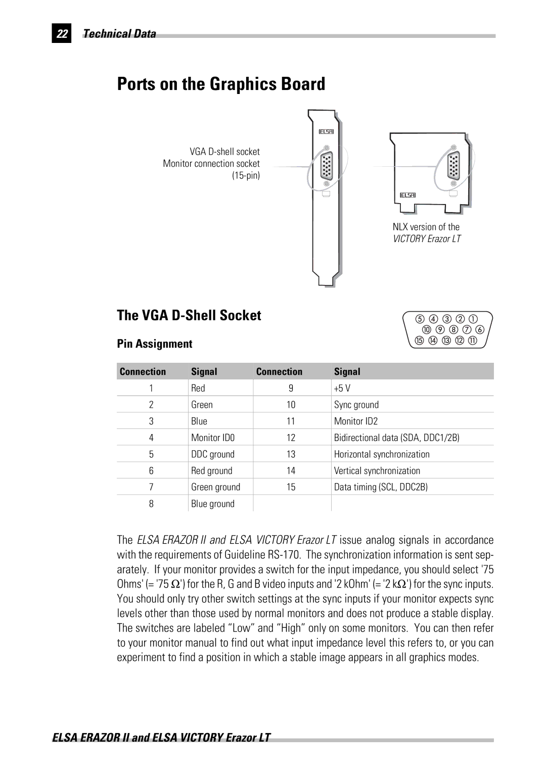
VGA D-shell socket Monitor connection socket (15-pin)
NLX version of the
VICTORY Erazor LT
The VGA D-Shell Socket
Pin Assignment
Connection | Signal | Connection | Signal |
1 | Red | 9 | +5 V |
| | | |
2 | Green | 10 | Sync ground |
| | | |
3 | Blue | 11 | Monitor ID2 |
| | | |
4 | Monitor ID0 | 12 | Bidirectional data (SDA, DDC1/2B) |
| | | |
5 | DDC ground | 13 | Horizontal synchronization |
| | | |
6 | Red ground | 14 | Vertical synchronization |
| | | |
7 | Green ground | 15 | Data timing (SCL, DDC2B) |
| | | |
8 | Blue ground | | |
| | | |
The ELSA ERAZOR II and ELSA VICTORY Erazor LT issue analog signals in accordance with the requirements of Guideline RS-170. The synchronization information is sent sep- arately. If your monitor provides a switch for the input impedance, you should select '75 Ohms' (= '75 Ω') for the R, G and B video inputs and '2 kOhm' (= '2 kΩ') for the sync inputs. You should only try other switch settings at the sync inputs if your monitor expects sync levels other than those used by normal monitors and does not produce a stable display. The switches are labeled “Low” and “High” only on some monitors. You can then refer to your monitor manual to find out what input impedance level this refers to, or you can experiment to find a position in which a stable image appears in all graphics modes.
ELSA ERAZOR II and ELSA VICTORY Erazor LT