INSTALLATION (continued)
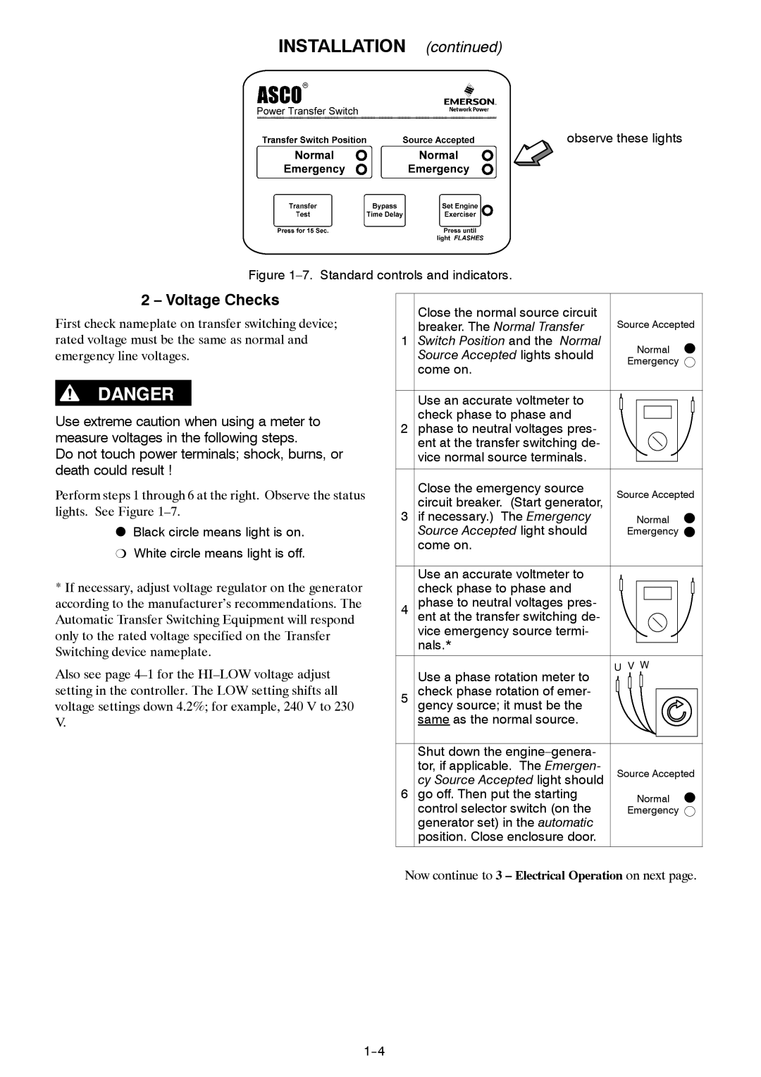
observe these lights
Figure 1–7. Standard controls and indicators.
2 – Voltage Checks
First check nameplate on transfer switching device; rated voltage must be the same as normal and emergency line voltages.
Use extreme caution when using a meter to measure voltages in the following steps.
Do not touch power terminals; shock, burns, or death could result !
Perform steps 1 through 6 at the right. Observe the status lights. See Figure
OBlack circle means light is on. P White circle means light is off.
*If necessary, adjust voltage regulator on the generator according to the manufacturer’s recommendations. The Automatic Transfer Switching Equipment will respond only to the rated voltage specified on the Transfer Switching device nameplate.
| Close the normal source circuit |
|
| breaker. The Normal Transfer | Source Accepted |
1 | Switch Position and the Normal | Normal |
| Source Accepted lights should | |
| Emergency | |
| come on. | |
|
| |
| Use an accurate voltmeter to |
|
| check phase to phase and |
|
2 phase to neutral voltages pres- |
| |
| ent at the transfer switching de- |
|
| vice normal source terminals. |
|
| Close the emergency source | Source Accepted |
| circuit breaker. (Start generator, | |
3 | if necessary.) The Emergency | Normal |
| Source Accepted light should | Emergency |
| come on. |
|
Use an accurate voltmeter to check phase to phase and
4phase to neutral voltages pres- ent at the transfer switching de- vice emergency source termi- nals.*
Also see page
Use a phase rotation meter to
U V W
setting in the controller. The LOW setting shifts all voltage settings down 4.2%; for example, 240 V to 230 V.
5 check phase rotation of emer- gency source; it must be the same as the normal source.
Shut down the |
|
tor, if applicable. The Emergen- | Source Accepted |
cy Source Accepted light should | |
6 go off. Then put the starting | Normal |
control selector switch (on the | Emergency |
generator set) in the automatic |
|
position. Close enclosure door. |
|
Now continue to 3 – Electrical Operation on next page.