INSTALLATION (continued)
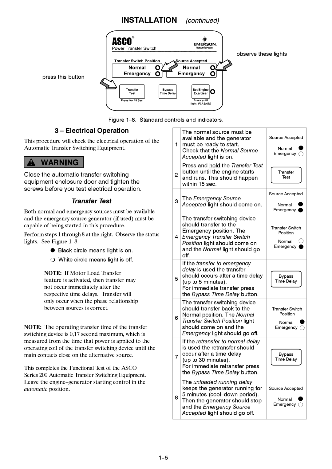
observe these lights
press this button
Figure 1–8. Standard controls and indicators.
3 – Electrical Operation
This procedure will check the electrical operation of the Automatic Transfer Switching Equipment.
Close the automatic transfer switching equipment enclosure door and tighten the screws before you test electrical operation.
Transfer Test
Both normal and emergency sources must be available and the emergency source generator (if used) must be capable of being started in this procedure.
Perform steps 1 through 8 at the right. Observe the status lights. See Figure
OBlack circle means light is on. P White circle means light is off.
NOTE: If Motor Load Transfer feature is activated, then transfer may not occur immediately after the respective time delays. Transfer will only occur when the phase relationship between sources is correct.
NOTE: The operating transfer time of the transfer switching device is 0,17 second maximum, which is measured from the time that power is applied to the operating coil of the transfer switching device until the main contacts close on the alternative source.
This completes the Functional Test of the ASCO Series 200 Automatic Transfer Switching Equipment. Leave the
| The normal source must be |
| |
| available and the generator | Source Accepted | |
1 must be ready to start. | Normal | ||
| Check that the Normal Source | ||
| Emergency | ||
| Accepted light is on. | ||
|
| ||
| Press and hold the Transfer Test |
| |
2 | button until the engine starts | Transfer | |
and runs. This should happen | Test | ||
| within 15 sec. |
| |
3 | The Emergency Source | Source Accepted | |
| |||
| Accepted light should come on. | Normal | |
|
| Emergency | |
| The transfer switching device |
| |
| should transfer to the | Transfer Switch | |
| Emergency position. The | ||
| Position | ||
4 | Emergency Transfer Switch | ||
Normal | |||
| Position light should come on | ||
| and the Normal light should go | Emergency | |
|
| ||
| off. |
| |
| If the transfer to emergency |
| |
| delay is used the transfer |
| |
5 | should occurs after a time delay | Bypass | |
(up to 5 minutes). | Time Delay | ||
| For immediate transfer press |
| |
| the Bypass Time Delay button. |
| |
| The transfer switching device |
| |
| should transfer back to the | Transfer Switch | |
6 | Normal position. The Normal | Position | |
Transfer Switch Position light | Normal | ||
| should come on and the | Emergency | |
| Emergency light should go off. |
| |
| If the retransfer to normal delay |
| |
| is used the retransfer should |
| |
7 | occur after a time delay | Bypass | |
(up to 30 minutes). | Time Delay | ||
| For immediate retransfer press |
| |
| the Bypass Time Delay button. |
| |
| The unloaded running delay |
| |
| keeps the generator running for | Source Accepted | |
8 | 5 minutes | Normal | |
Then the generator should stop | |||
| and the Emergency Source | Emergency | |
|
| ||
| Accepted light should go off. |
| |
