SECTION 3 TESTING & SERVICE
PREVENTIVE MAINTENANCE
Reasonable care in preventive maintenance will insure high reliability and long life for the automatic transfer switch.
Operate the switch at least once a month. Perform this four step Electrical Operation Test. This is a test with load transfer.
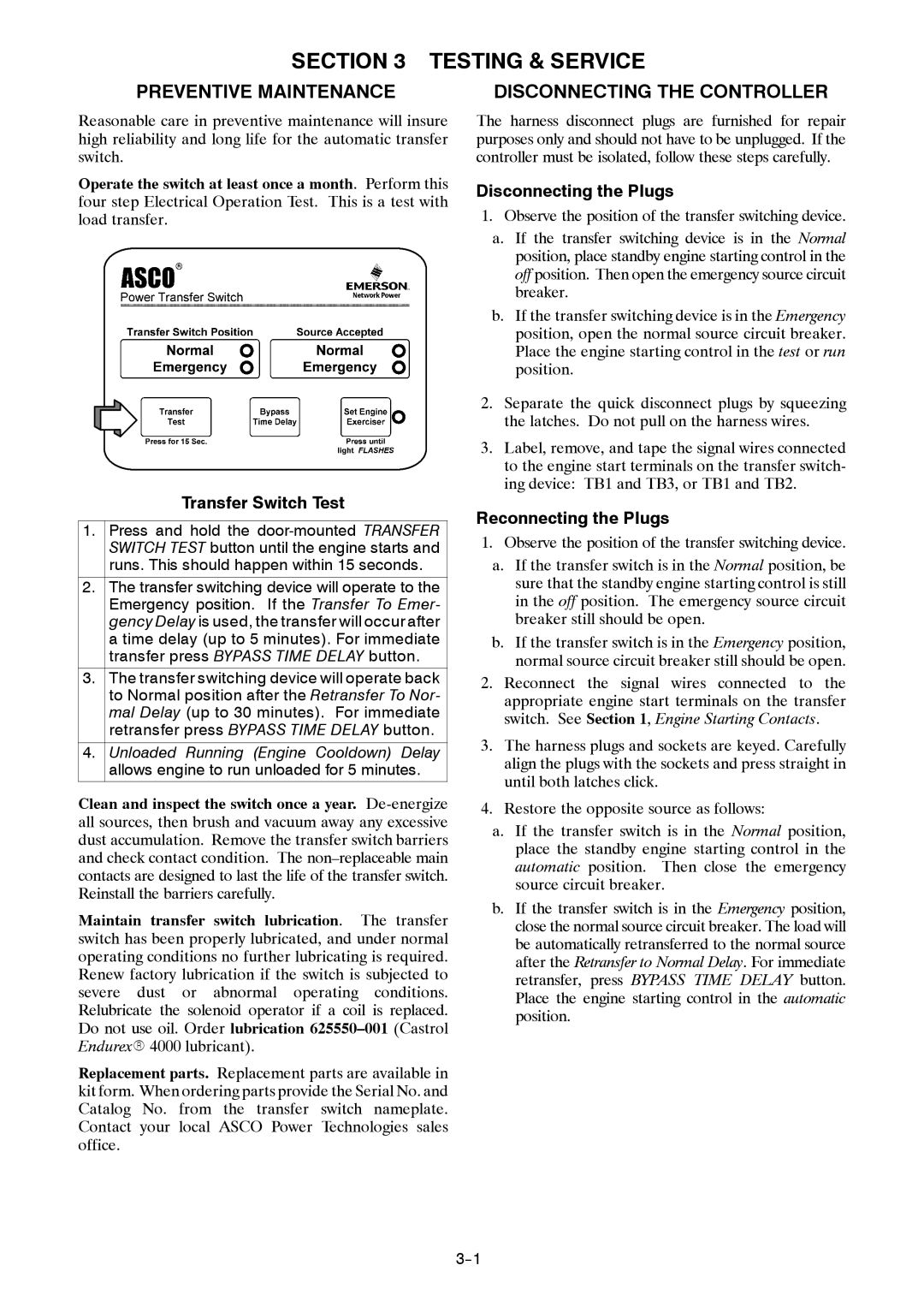
Transfer Switch Test
1.Press and hold the
2.The transfer switching device will operate to the Emergency position. If the Transfer To Emer- gency Delay is used, the transfer will occur after a time delay (up to 5 minutes). For immediate transfer press BYPASS TIME DELAY button.
3.The transfer switching device will operate back to Normal position after the Retransfer To Nor- mal Delay (up to 30 minutes). For immediate retransfer press BYPASS TIME DELAY button.
4.Unloaded Running (Engine Cooldown) Delay allows engine to run unloaded for 5 minutes.
Clean and inspect the switch once a year.
Maintain transfer switch lubrication. The transfer switch has been properly lubricated, and under normal operating conditions no further lubricating is required. Renew factory lubrication if the switch is subjected to severe dust or abnormal operating conditions. Relubricate the solenoid operator if a coil is replaced. Do not use oil. Order lubrication
Replacement parts. Replacement parts are available in kit form. When ordering parts provide the Serial No. and Catalog No. from the transfer switch nameplate. Contact your local ASCO Power Technologies sales office.
DISCONNECTING THE CONTROLLER
The harness disconnect plugs are furnished for repair purposes only and should not have to be unplugged. If the controller must be isolated, follow these steps carefully.
Disconnecting the Plugs
1.Observe the position of the transfer switching device.
a.If the transfer switching device is in the Normal position, place standby engine starting control in the off position. Then open the emergency source circuit breaker.
b.If the transfer switching device is in the Emergency position, open the normal source circuit breaker. Place the engine starting control in the test or run position.
2.Separate the quick disconnect plugs by squeezing the latches. Do not pull on the harness wires.
3.Label, remove, and tape the signal wires connected to the engine start terminals on the transfer switch- ing device: TB1 and TB3, or TB1 and TB2.
Reconnecting the Plugs
1.Observe the position of the transfer switching device.
a.If the transfer switch is in the Normal position, be sure that the standby engine starting control is still in the off position. The emergency source circuit breaker still should be open.
b.If the transfer switch is in the Emergency position, normal source circuit breaker still should be open.
2.Reconnect the signal wires connected to the appropriate engine start terminals on the transfer switch. See Section 1, Engine Starting Contacts.
3.The harness plugs and sockets are keyed. Carefully align the plugs with the sockets and press straight in until both latches click.
4.Restore the opposite source as follows:
a.If the transfer switch is in the Normal position, place the standby engine starting control in the automatic position. Then close the emergency source circuit breaker.
b.If the transfer switch is in the Emergency position, close the normal source circuit breaker. The load will be automatically retransferred to the normal source after the Retransfer to Normal Delay. For immediate retransfer, press BYPASS TIME DELAY button. Place the engine starting control in the automatic position.