INSTALLATION (continued)
Functional Test
The Functional Test consists of three checks: manual operation, voltage checks, and electrical operation.
NOTICE
Do these checks in the order presented to avoid damaging the automatic transfer switching equipment.
Read all instructions on the Wiring Diagrams and labels affixed to the ATS. Note the control features that are provided and review their operation before proceeding.
1 – Manual Operation
A detachable manual operator handle is provided on the Transfer Switching device for maintenance purposes only. Manual operation of the transfer switching device must be checked before it is operated electrically.
Do not manually operate the transfer switching device until both power sources are disconnected: open both circuit breakers.
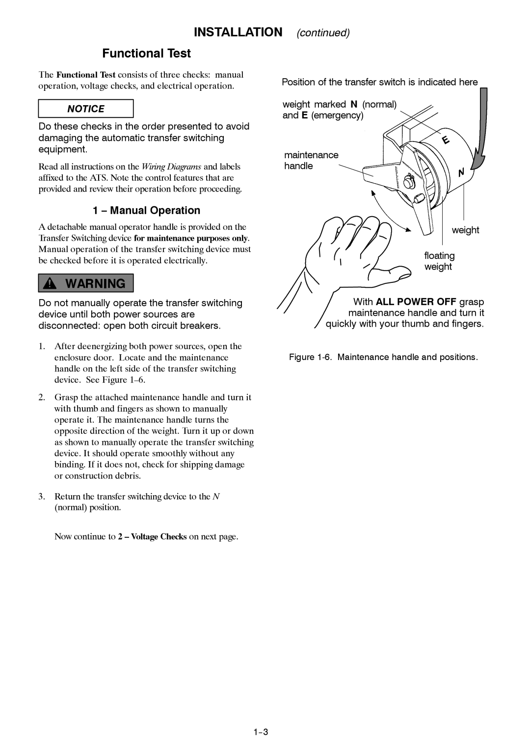
Position of the transfer switch is indicated here
weight marked N (normal) and E (emergency)
maintenance handle
weight
floating weight
With ALL POWER OFF grasp maintenance handle and turn it quickly with your thumb and fingers.
1.After deenergizing both power sources, open the enclosure door. Locate and the maintenance handle on the left side of the transfer switching device. See Figure
2.Grasp the attached maintenance handle and turn it with thumb and fingers as shown to manually operate it. The maintenance handle turns the opposite direction of the weight. Turn it up or down as shown to manually operate the transfer switching device. It should operate smoothly without any binding. If it does not, check for shipping damage or construction debris.
3.Return the transfer switching device to the N (normal) position.
Figure 1-6. Maintenance handle and positions.
Now continue to 2 – Voltage Checks on next page.