00809-0400-4728, Rev AA June
Reference Manual
Page
Table of Contents
TOC-2
Specifications Reference Data
Appendix a
Appendix B
Customer Central National Response Center International
Rosemount Temperature Transmitters
Page
Process leaks could result in death or serious injury
Safety Messages
Section Introduction
Explosions could result in death or serious injury
Manual
Overview
Transmitter
Considerations
Above
22 20 815 C 1500 F Oven Temperature
250 C 482 F Oven Temperature 5 6 7 8 Extension Length
Example
Section Installation
Bench Calibration?
Within Specifications? Refer to Configuration
Simulate Sensor Input
Rail asymmetric
From draining into the transmitter housing
Mounting
Mounting a 644H to a DIN Rail
Typical European Installation
Installation
Head Mount Transmitter with DIN Plate Style Sensor
Head Mount Transmitter with Threaded Sensor
Typical North American Installation
Installing the LCD Display
LCD Display Installation
Power terminals does not drop below 9 Vdc
Wiring
Thermocouple or Millivolt Inputs
Sensor Connections
Sensor Input Approximate Basic Error
Sensor Lead Wire Resistance Effect- RTD Input
RTD or Ohm Inputs
Error due to amb. temp. var. of ± 25 C
Pt100 2-wire RTD
Ungrounded Thermocouple, mV, and RTD/Ohm Inputs
Power Supply
Foundation fieldbus Installation
Ground the Transmitter
Grounded Thermocouple Inputs
Overview Safety Messages
Section Configuration
Auto
General Block Information
Device Description Node Address
Modes
Resource Transducer Analog Input Other
Link Active Scheduler Block Installation
Foundation Fieldbus Function Blocks
Capabilities
Reports
Features
Resource Block
Unicode
PlantWeb Alerts
Featuressel
Failedalarms
Maxnotify
Failedmask
Maintalarms
Recommended Actions for PlantWeb Alerts
Advisory Alarms
Recommendedaction
Damping
Configure the AI block
Sensor Transducer Block
Analog Input AI Function Block
Ltype
Pressure Channel Temperature Channel
Xdscale and Outscale
Transducer Block
Configuration Examples
Filtering
Process Alarms
Outd
Alarmtype
PARAMINDEX#1
LCD Transducer Block
Displayparamsel
BLKTYPE#1
CUSTOMUNITS#1
Operation and Maintenance
Overview
UNITSTYPE#1
Troubleshooting guide
Troubleshooting Guides
Problems with communications flowchart
Calpointlo + Calminspan
Sensor Transducer Block Xderr messages
Diagnostics
Recall Factory Trim
Block Blockerr messages
Calibrationerr
Description
Simulate
Manual Mode
Status
Simulation
00809-0400-4728, Rev AA June AI Blockerr Conditions
Troubleshooting AI block
Power Up
Symptom Possible Causes Recommended Actions
Condition Name
Block Errors
8lists conditions reported in the Blockerr parameter
10. Resource Block
Symptom Possible Causes Recommended Action
Self Test Procedure for the LCD
Auto
Specifications
Appendix a Specifications Reference Data
FunctionalInputs
Physical
Performance
2 σ -1 σ
Foundation Fieldbus Specifications
Rosemount Conformance to Specifications
Function Blocks
Software Upgrade in the Field
Power Supply
Alarms
Backup Link Active Scheduler LAS
Table A-1. Rosemount 644 Input Options and Accuracy
Accuracy
Accuracy Example
Table A-2. Ambient Temperature Effect
Ambient Temperature Effect
Thermocouples
Temperature Effects Examples
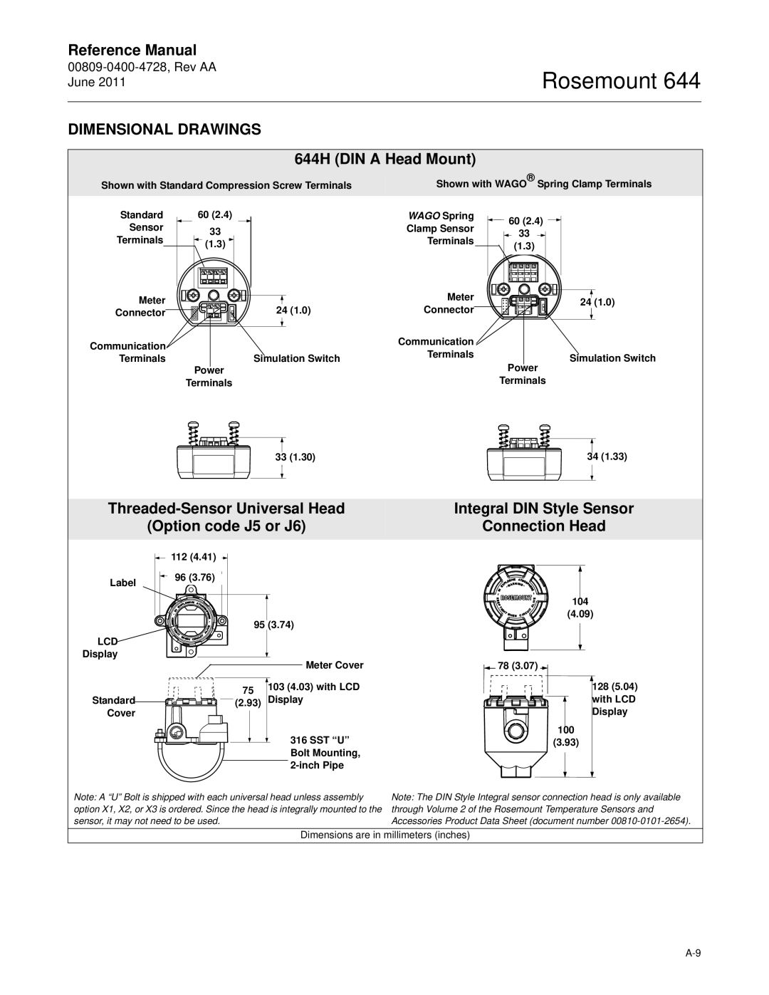
644H DIN a Head Mount
Dimensional Drawings
June
LCD Display
Mounting
00809-0400-4728, Rev AA
LCD Display Cover
Sanitary Housing Covers
Ring 76.2 27.9 74.4 25.4 44.5 70.0
Options
Ordering Information
Enclosure Options Standard
Configuration Standard
Alarm Level Configuration Standard
Assemble To Options Standard
Considerations
Tagging
Configuration tool
Transmitter Configuration
With DeltaV, with AMS, or other Foundation fieldbus host or
Standard Block Configuration
Standard Foundation fieldbus Configuration
Custom Configuration
Requirements Option Code Specification
Appendix B Product Certifications
CE Electromagnetic Compatibility Compliance Testing
Atex Directive 94/9/EC
North American Certifications
Hazardous Locations Certificates
Rosemount 644 with Foundation fieldbus
Special Conditions for Safe Use
Loop/Power Terminals
Fisco Loop/Power Terminals
European Certifications
Fisco Group IIC To 80 C
Temperature Class
IECEx Certifications
To 60 C
Schedule of Limitations
Table B-3. Entity Parameters
Transmitter I.S Transmitter Fisco Sensor
Transmitter Sensor
Description Group Code
Ukraine Gost
Pattern Approval for Measuring Instruments See Certificate
Approval Temp
Installation Drawings
Rosemount
Rosemount
Rosemount
00809-0100-4728, Rev AA June Sheet 2
00809-0100-4728, Rev AA June Sheet 3
00809-0100-4728, Rev AA June
00809-0100-4728, Rev AA June Sheet 2
Rosemount
Rosemount
00809-0100-4728, Rev AA June Sheet 2
00809-0100-4728, Rev AA June Sheet 3
Appendix C Foundation fieldbus Block Information
Basic Setup Resource Block
Definition
Index
Parameters and Descriptions
Maintenable
Failedenable
Features
Featuresel
00809-0400-4728, Rev AA
Parameters Descriptions
Sensor Transducer Block
Description Effects transmitter operation
Calvandusencoeff
Primaryvaluerange
Primaryvaluetype
Sensrdetailedstatus
Transducertype
Xderror
SESNOR1DAMPING
Transducerdirectory
Convert Calc
Analog Measurement Access
Analog Input AI Function Block
Outd Cutoff Filter
Ackoption
AI Parameter Table
Lolopri
Table C-4. LCD Transducer Block Parameters and Descriptions
LCD Transducer Block
Parameter Index Description
Table C-5. PID Block Parameters and Descriptions
PID Block
Parameter Index
Index
DIN Rail Threaded Sensor
Ungrounded Wiring MODEBLK.TARGET
Bad Uncertain
Lolim Lololim Lolopri Lopri Lower Trim Method
Direct Zero Trim
Limited Man Mode Unicode UNITSTYPE# Upper Trim Method
Grounded Ungrounded Wiring
Security Self Test
Index-4
Page
Emerson Process Management Rosemount Inc
Temperature GmbH Pacific Private Limited

![]() 112 (4.41)
112 (4.41) ![]()
![]()
![]() 78 (3.07)
78 (3.07) ![]()
