Reference Manual
00809-0400-4728, Rev AA June 2011
Rosemount 644
SENSOR TRANSDUCER BLOCK
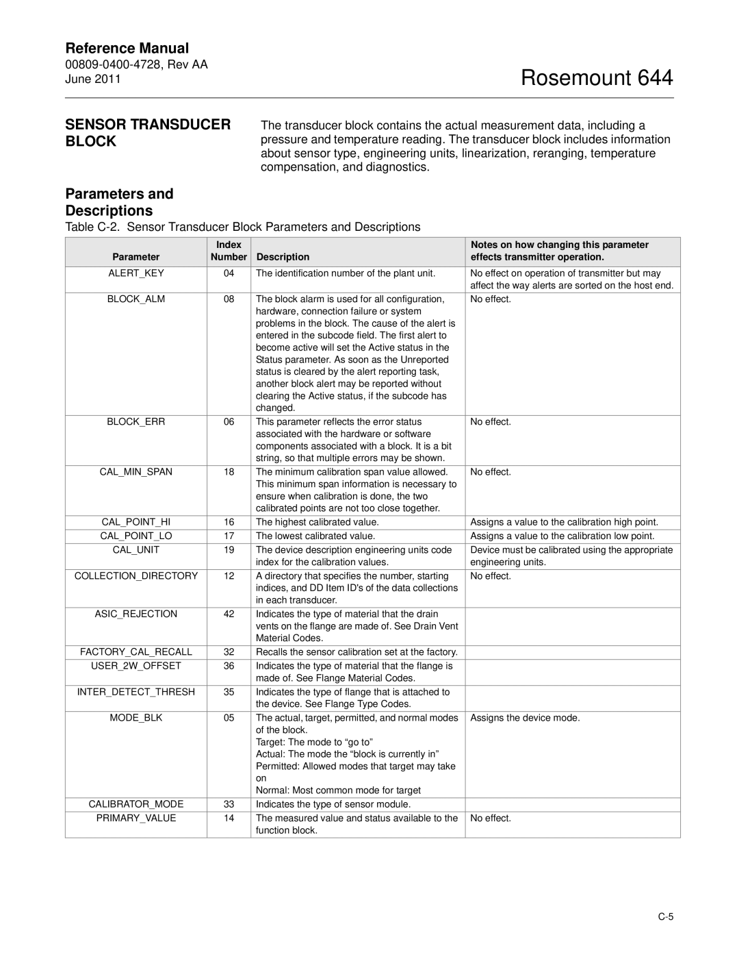
The transducer block contains the actual measurement data, including a pressure and temperature reading. The transducer block includes information about sensor type, engineering units, linearization, reranging, temperature compensation, and diagnostics.
Parameters and
Descriptions
Table
| Index |
| Notes on how changing this parameter |
Parameter | Number | Description | effects transmitter operation. |
ALERT_KEY | 04 | The identification number of the plant unit. | No effect on operation of transmitter but may |
|
|
| affect the way alerts are sorted on the host end. |
BLOCK_ALM | 08 | The block alarm is used for all configuration, | No effect. |
|
| hardware, connection failure or system |
|
|
| problems in the block. The cause of the alert is |
|
|
| entered in the subcode field. The first alert to |
|
|
| become active will set the Active status in the |
|
|
| Status parameter. As soon as the Unreported |
|
|
| status is cleared by the alert reporting task, |
|
|
| another block alert may be reported without |
|
|
| clearing the Active status, if the subcode has |
|
|
| changed. |
|
BLOCK_ERR | 06 | This parameter reflects the error status | No effect. |
|
| associated with the hardware or software |
|
|
| components associated with a block. It is a bit |
|
|
| string, so that multiple errors may be shown. |
|
CAL_MIN_SPAN | 18 | The minimum calibration span value allowed. | No effect. |
|
| This minimum span information is necessary to |
|
|
| ensure when calibration is done, the two |
|
|
| calibrated points are not too close together. |
|
CAL_POINT_HI | 16 | The highest calibrated value. | Assigns a value to the calibration high point. |
CAL_POINT_LO | 17 | The lowest calibrated value. | Assigns a value to the calibration low point. |
CAL_UNIT | 19 | The device description engineering units code | Device must be calibrated using the appropriate |
|
| index for the calibration values. | engineering units. |
COLLECTION_DIRECTORY | 12 | A directory that specifies the number, starting | No effect. |
|
| indices, and DD Item ID's of the data collections |
|
|
| in each transducer. |
|
ASIC_REJECTION | 42 | Indicates the type of material that the drain |
|
|
| vents on the flange are made of. See Drain Vent |
|
|
| Material Codes. |
|
FACTORY_CAL_RECALL | 32 | Recalls the sensor calibration set at the factory. |
|
USER_2W_OFFSET | 36 | Indicates the type of material that the flange is |
|
|
| made of. See Flange Material Codes. |
|
INTER_DETECT_THRESH | 35 | Indicates the type of flange that is attached to |
|
|
| the device. See Flange Type Codes. |
|
MODE_BLK | 05 | The actual, target, permitted, and normal modes | Assigns the device mode. |
|
| of the block. |
|
|
| Target: The mode to “go to” |
|
|
| Actual: The mode the “block is currently in” |
|
|
| Permitted: Allowed modes that target may take |
|
|
| on |
|
|
| Normal: Most common mode for target |
|
CALIBRATOR_MODE | 33 | Indicates the type of sensor module. |
|
PRIMARY_VALUE | 14 | The measured value and status available to the | No effect. |
|
| function block. |
|