Quick Installation Guide
Rosemount 8712 / 8700 Series
If leakage has not stopped at the suggested torque values, the bolts can be tightened in additional 10% increments until the joint stops leaking, or until the measured torque value reaches the maximum torque value of the bolts. Practical consideration for the integrity of the liner often leads the user to distinct torque values to stop leakage due to the unique combinations of flanges, bolts, gaskets, and sensor liner material.
Check for leaks at the flanges after tightening the bolts. Failure to use the correct tightening methods can result in severe damage. Sensors require a second tightening 24 hours after the initial installation. Over time, sensor liner materials may deform under pressure.
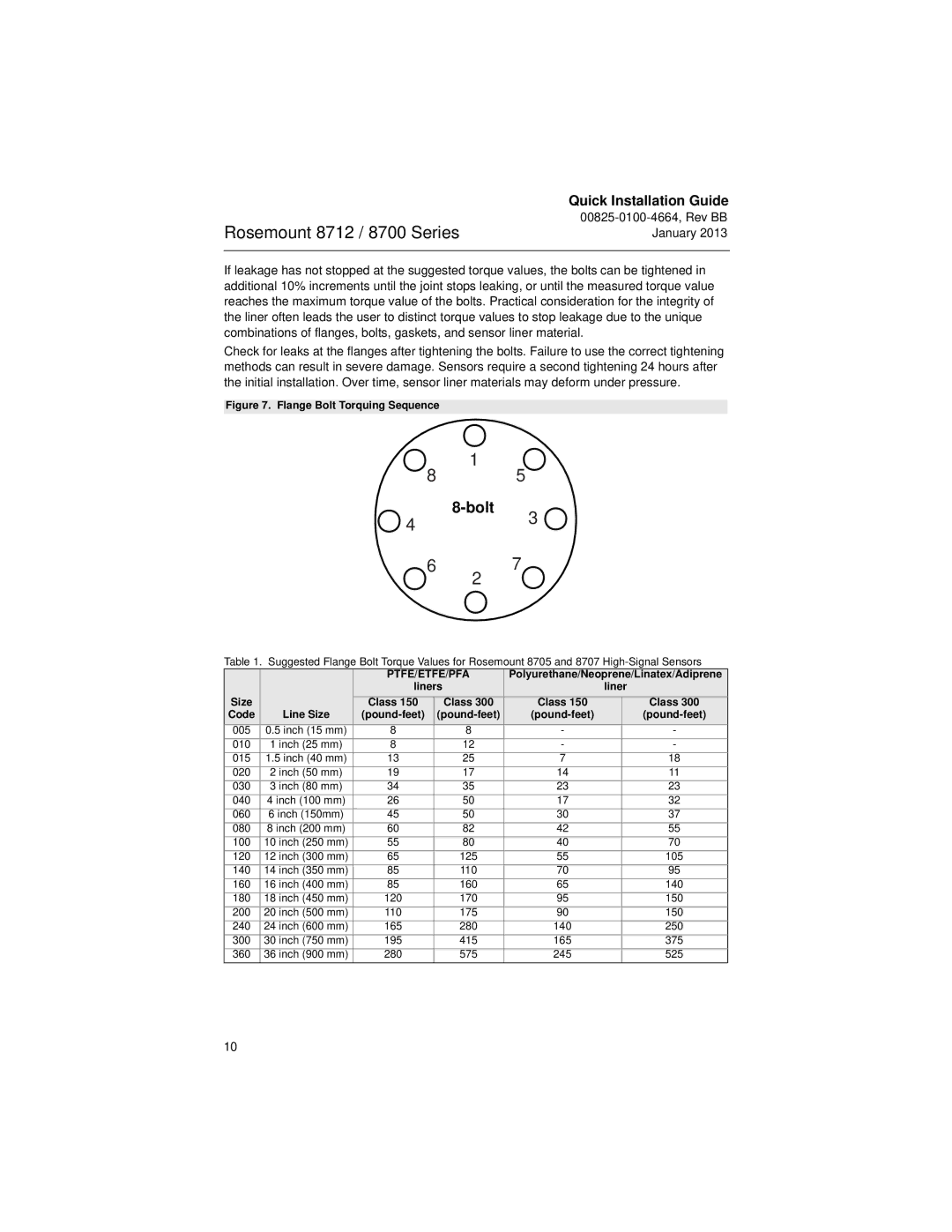
Figure 7. Flange Bolt Torquing Sequence
1
8 5
4 |
| 3 |
| ||
|
|
67
2
Table 1. Suggested Flange Bolt Torque Values for Rosemount 8705 and 8707
|
| PTFE/ETFE/PFA | Polyurethane/Neoprene/Linatex/Adiprene | |||
|
| liners |
| liner | ||
Size |
| Class 150 | Class 300 | Class 150 |
| Class 300 |
Code | Line Size |
|
| |||
005 | 0.5 inch (15 mm) | 8 | 8 | - |
| - |
010 | 1 inch (25 mm) | 8 | 12 | - |
| - |
015 | 1.5 inch (40 mm) | 13 | 25 | 7 |
| 18 |
020 | 2 inch (50 mm) | 19 | 17 | 14 |
| 11 |
030 | 3 inch (80 mm) | 34 | 35 | 23 |
| 23 |
040 | 4 inch (100 mm) | 26 | 50 | 17 |
| 32 |
060 | 6 inch (150mm) | 45 | 50 | 30 |
| 37 |
080 | 8 inch (200 mm) | 60 | 82 | 42 |
| 55 |
100 | 10 inch (250 mm) | 55 | 80 | 40 |
| 70 |
120 | 12 inch (300 mm) | 65 | 125 | 55 |
| 105 |
140 | 14 inch (350 mm) | 85 | 110 | 70 |
| 95 |
160 | 16 inch (400 mm) | 85 | 160 | 65 |
| 140 |
180 | 18 inch (450 mm) | 120 | 170 | 95 |
| 150 |
200 | 20 inch (500 mm) | 110 | 175 | 90 |
| 150 |
240 | 24 inch (600 mm) | 165 | 280 | 140 |
| 250 |
300 | 30 inch (750 mm) | 195 | 415 | 165 |
| 375 |
360 | 36 inch (900 mm) | 280 | 575 | 245 |
| 525 |
10