Communication
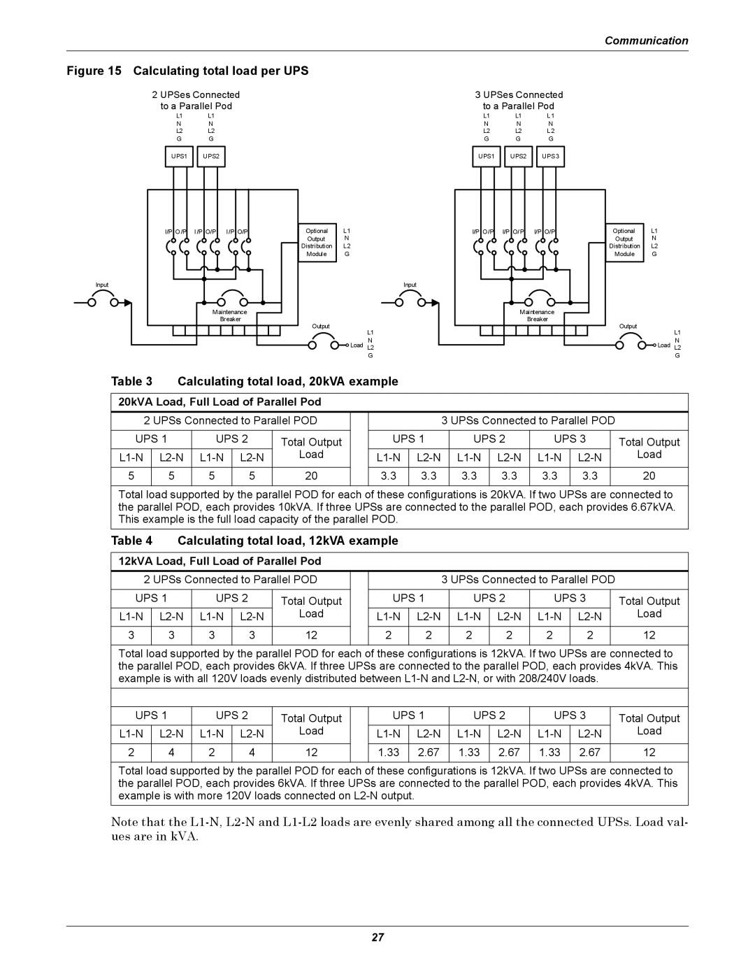
Figure 15 Calculating total load per UPS
Input
2 UPSes Connected to a Parallel Pod
L1 | L1 |
N | N |
L2 | L2 |
GG
UPS1 UPS2
I/P O/P I/P O/P I/P O/P
Maintenance
Breaker
Optional L1
Output N
Distribution L2
Module G
Input
Output
L1
N
![]() Load L2
Load L2
G
3 UPSes Connected to a Parallel Pod
L1 |
| L1 |
| L1 |
N |
| N |
| N |
L2 |
| L2 |
| L2 |
G |
| G |
| G |
|
|
|
|
|
UPS1 |
| UPS2 |
| UPS3 |
|
|
|
|
|
I/P O/P I/P O/P I/P O/P
Maintenance
Breaker
Optional L1
Output N
Distribution L2
Module G
Output
L1
N
![]() Load L2
Load L2
G
Table 3 | Calculating total load, 20kVA example |
|
|
|
|
|
|
|
| |||||||
|
|
|
|
|
|
|
|
|
|
|
|
|
|
| ||
20kVA Load, Full Load of Parallel Pod |
|
|
|
|
|
|
|
|
|
| ||||||
| 2 UPSs Connected to Parallel POD |
|
|
| 3 UPSs Connected to Parallel POD |
| ||||||||||
|
|
|
|
|
|
|
|
|
|
|
|
|
|
| ||
UPS 1 |
| UPS 2 | Total Output |
| UPS 1 |
| UPS 2 | UPS 3 |
| Total Output | ||||||
| Load |
|
|
| Load | |||||||||||
|
|
|
|
|
|
|
|
|
|
|
|
|
|
|
|
|
5 |
| 5 |
| 5 | 5 | 20 |
| 3.3 | 3.3 |
| 3.3 | 3.3 | 3.3 | 3.3 |
| 20 |
|
|
|
|
|
|
|
|
|
|
|
|
| ||||
Total load supported by the parallel POD for each of these configurations is 20kVA. If two UPSs are connected to | ||||||||||||||||
the parallel POD, each provides 10kVA. If three UPSs are connected to the parallel POD, each provides 6.67kVA. | ||||||||||||||||
This example is the full load capacity of the parallel POD. |
|
|
|
|
|
|
|
| ||||||||
Table 4 | Calculating total load, 12kVA example |
|
|
|
|
|
|
|
| |||||||
|
|
|
|
|
|
|
|
|
|
|
|
|
|
|
| |
12kVA Load, Full Load of Parallel Pod |
|
|
|
|
|
|
|
|
|
|
| |||||
2 UPSs Connected to Parallel POD |
|
|
|
| 3 UPSs Connected to Parallel POD |
| ||||||||||
|
|
|
|
|
|
|
|
|
|
|
|
|
| |||
UPS 1 | UPS 2 | Total Output |
| UPS 1 |
| UPS 2 | UPS 3 |
| Total Output | |||||||
| Load |
|
|
|
| Load | ||||||||||
|
|
|
|
|
|
|
|
|
|
|
|
|
|
|
|
|
3 |
| 3 | 3 | 3 | 12 |
| 2 |
| 2 |
| 2 | 2 | 2 | 2 |
| 12 |
|
|
|
|
|
|
|
|
|
|
|
|
| ||||
Total load supported by the parallel POD for each of these configurations is 12kVA. If two UPSs are connected to | ||||||||||||||||
the parallel POD, each provides 6kVA. If three UPSs are connected to the parallel POD, each provides 4kVA. This | ||||||||||||||||
example is with all 120V loads evenly distributed between |
| |||||||||||||||
|
|
|
|
|
|
|
|
|
|
|
|
|
|
|
|
|
UPS 1 | UPS 2 | Total Output |
| UPS 1 |
| UPS 2 | UPS 3 |
| Total Output | |||||||
| Load |
|
|
| Load | |||||||||||
|
|
|
|
|
|
|
|
|
|
|
|
|
|
|
|
|
2 |
| 4 | 2 | 4 | 12 |
| 1.33 |
| 2.67 |
| 1.33 | 2.67 | 1.33 | 2.67 |
| 12 |
|
|
|
|
|
|
|
|
|
|
|
|
| ||||
Total load supported by the parallel POD for each of these configurations is 12kVA. If two UPSs are connected to | ||||||||||||||||
the parallel POD, each provides 6kVA. If three UPSs are connected to the parallel POD, each provides 4kVA. This | ||||||||||||||||
example is with more 120V loads connected on |
|
|
|
|
|
|
|
| ||||||||
Note that the
27
