Installation
5.2Paralleling System Connections
The Liebert
! WARNING
Risk of electric shock. May cause property damage, personal injury or death.
Lethal voltages may exist within the UPS and parallel POD as long as the UPS is connected.
Ensure that all the UPS are disconnected and that the power is off before working within the parallel POD. Check the circuits with a voltmeter.
In addition, make sure all the internal batteries within the Liebert
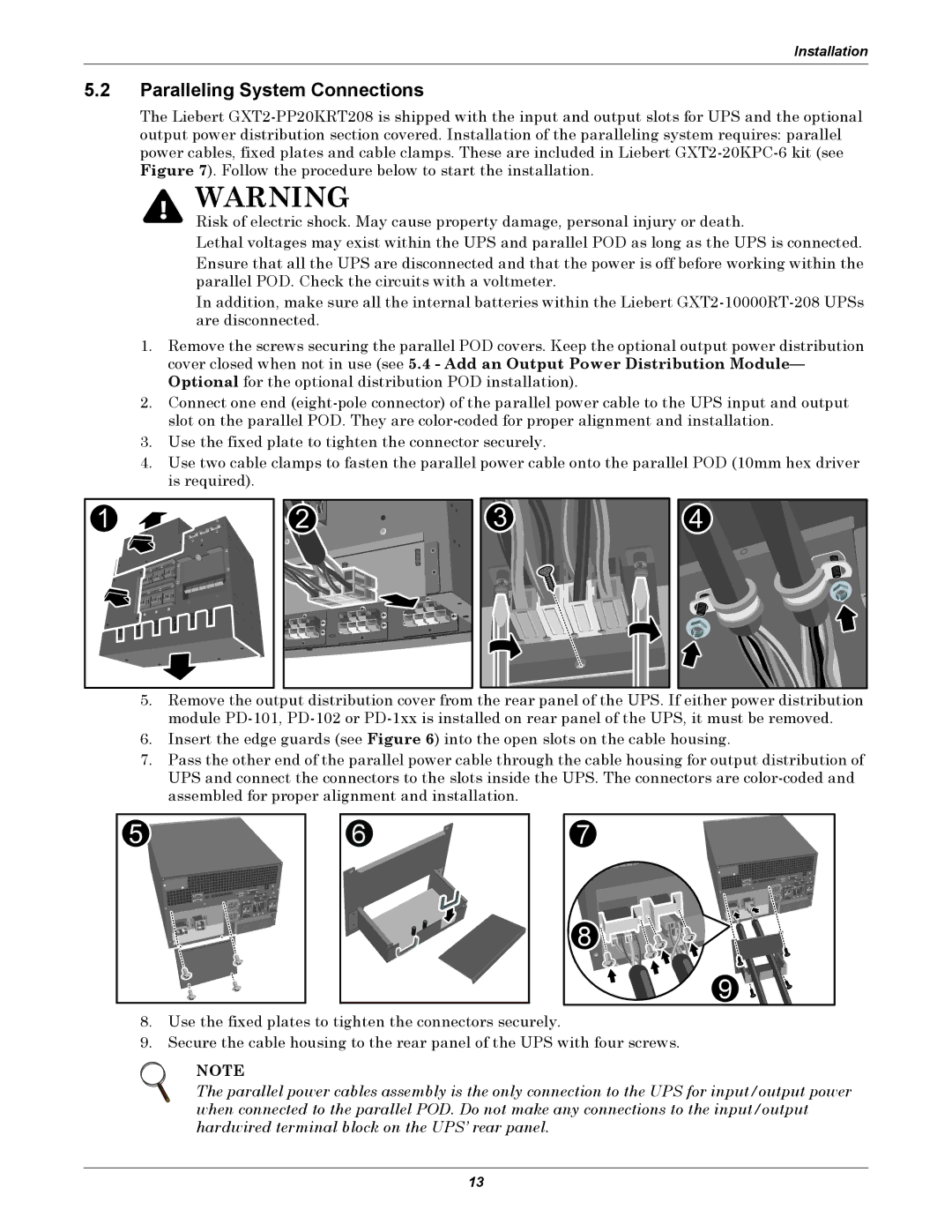
1.Remove the screws securing the parallel POD covers. Keep the optional output power distribution cover closed when not in use (see 5.4 - Add an Output Power Distribution Module— Optional for the optional distribution POD installation).
2.Connect one end
3.Use the fixed plate to tighten the connector securely.
4.Use two cable clamps to fasten the parallel power cable onto the parallel POD (10mm hex driver is required).
1 |
2 |
3 |
4 |
5.Remove the output distribution cover from the rear panel of the UPS. If either power distribution module
6.Insert the edge guards (see Figure 6) into the open slots on the cable housing.
7.Pass the other end of the parallel power cable through the cable housing for output distribution of UPS and connect the connectors to the slots inside the UPS. The connectors are
5 |
6 |
7 |
8 |
9 |
8. Use the fixed plates to tighten the connectors securely.
9. Secure the cable housing to the rear panel of the UPS with four screws.
NOTE
The parallel power cables assembly is the only connection to the UPS for input/output power when connected to the parallel POD. Do not make any connections to the input/output hardwired terminal block on the UPS’ rear panel.
13
