Cable Installation
6.7Input and Output Wiring
NOTE
Input wiring must be installed using conduit.
208 input voltage
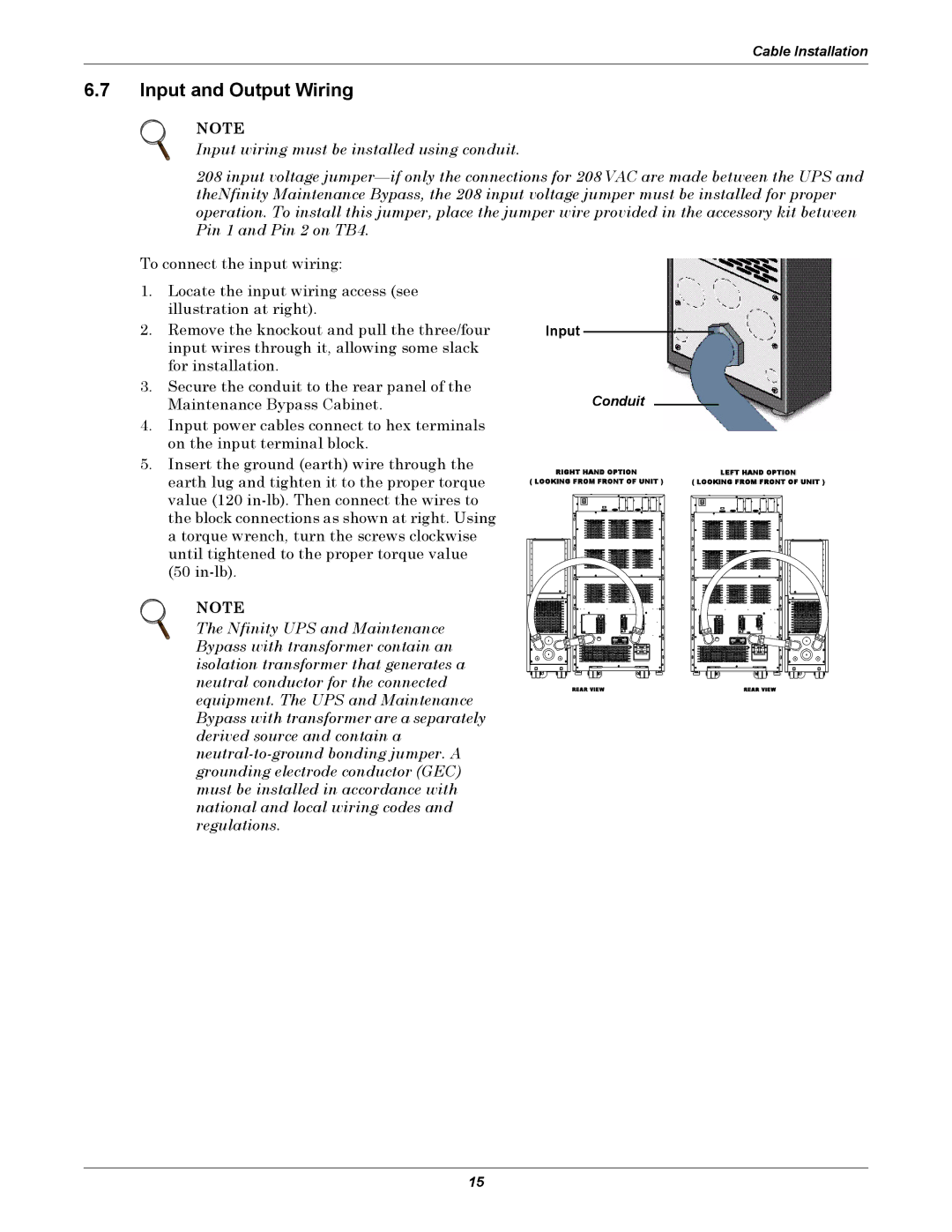
To connect the input wiring:
1.Locate the input wiring access (see illustration at right).
2.Remove the knockout and pull the three/four input wires through it, allowing some slack for installation.
3.Secure the conduit to the rear panel of the Maintenance Bypass Cabinet.
4.Input power cables connect to hex terminals on the input terminal block.
5.Insert the ground (earth) wire through the earth lug and tighten it to the proper torque value (120
NOTE
The Nfinity UPS and Maintenance Bypass with transformer contain an isolation transformer that generates a neutral conductor for the connected equipment. The UPS and Maintenance Bypass with transformer are a separately derived source and contain a
Input
Conduit
RIGHT HAND OPTION | LEFT HAND OPTION |
( LOOKING FROM FRONT OF UNIT ) | ( LOOKING FROM FRONT OF UNIT ) |
REAR VIEW | REAR VIEW |
15