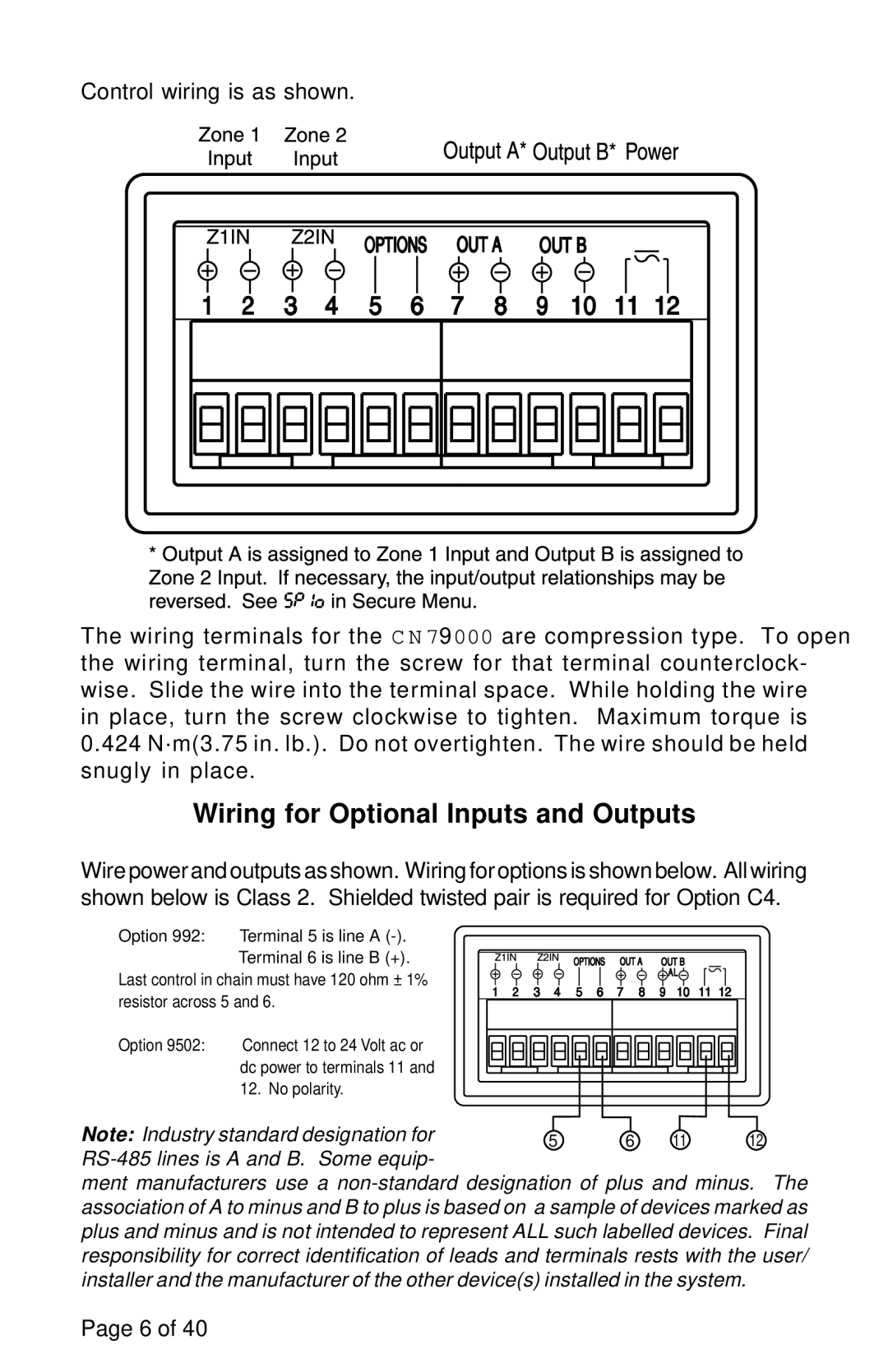
Control wiring is as shown.
The wiring terminals for the C N 79000 are compression type. To open the wiring terminal, turn the screw for that terminal counterclock- wise. Slide the wire into the terminal space. While holding the wire
in place, turn the screw clockwise to tighten. Maximum torque is 0.424 N·m(3.75 in. lb.). Do not overtighten. The wire should be held snugly in place.
Wiring for Optional Inputs and Outputs
Wire power and outputs as shown. Wiring for options is shown below. All wiring shown below is Class 2. Shielded twisted pair is required for Option C4.
Option 992: Terminal 5 is line A
Last control in chain must have 120 ohm ± 1% resistor across 5 and 6.
Option 9502: Connect 12 to 24 Volt ac or dc power to terminals 11 and 12. No polarity.
Note: Industry standard designation for | 5 | 6 11 | 12 |
|
|
|
|
ment manufacturers use a
Page 6 of 40
