Wiring for 4 to 20mA Transmitter inputs
WARNING: The inputs of the instrument are not isolated from each other. The input sources must be isolated from each other. Process inputs may not share a common external ground.
FAILURE TO OBSERVE THIS WARNING MAY CAUSE DANGEROUS OR LETHAL VOLTAGES TO BE PRESENT IN THE INSTRUMENT WHICH MAY CAUSE SERIOUS INJURY OR DEATH.
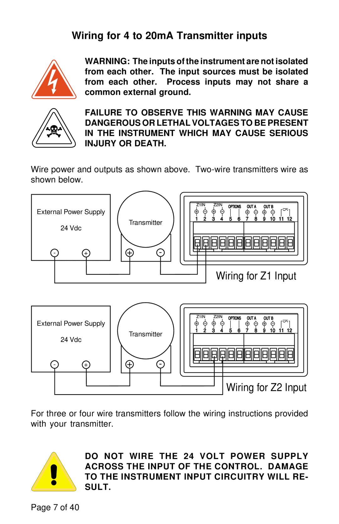
Wire power and outputs as shown above.
External Power Supply
24 Vdc
- | + |
External Power Supply
24 Vdc
-+
Transmitter
+-
Wiring for Z1 Input
Transmitter
+-
Wiring for Z2 Input
For three or four wire transmitters follow the wiring instructions provided with your transmitter.
DO NOT WIRE THE 24 VOLT POWER SUPPLY ACROSS THE INPUT OF THE CONTROL. DAMAGE TO THE INSTRUMENT INPUT CIRCUITRY WILL RE- SULT.
Page 7 of 40