4.2MRLDS Setup
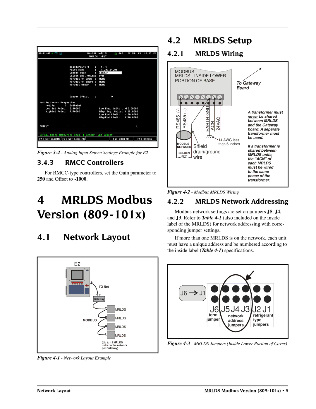
4.2.1MRLDS Wiring
MODBUS
MRLDS - INSIDE LOWER
PORTION OF BASE | To Gateway |
| |
| Board |
Figure 3-4 - Analog Input Screen Settings Example for E2
3.4.3RMCC Controllers
For
) ) | D |
| ||
NG |
| |||
- | + |
| ||
( |
| |||
| ( |
| ||
485 | 5 |
| ||
ARHTE ACN 24VAC | ||||
8 | ||||
4 | ||||
S |
| |||
R | ||||
| RS | |||
|
|
| 14 AWG less | |
MODBUS |
| than 6 inches | ||
NETWORK Shield |
| |||
BELDEN | drain/ground | |||
| 8761 | wire |
| |
|
|
| ||
A transformer must never be shared between MRLDS and the Gateway board. A separate transformer must be used.
If a transformer is shared between MRLDS units, the “ACN” of each MRLDS must be wired to the same phase of the transformer.
4MRLDS Modbus Version (809-101x)
4.1Network Layout
E2 |
|
|
| |
+ |
|
|
| |
- | I/O Net |
| ||
|
| |||
| - + |
|
| |
| Gateway |
|
| |
|
| + | MRLDS | |
|
| - | ||
|
| + | MRLDS | |
MODBUS | - | |||
| ||||
+ |
| MRLDS | |
- |
|
| |
+ |
|
| MRLDS |
|
| ||
- |
|
| |
(Up to 12 MRLDS units on the network per Gateway)
Figure 4-1 - Network Layout Example
Figure 4-2 - Modbus MRLDS Wiring
4.2.2MRLDS Network Addressing
Modbus network settings are set on jumpers J5, J4, and J3. Refer to Table
If more than one MRLDS is on the network, each unit must have a unique address and be numbered according to the inside label (Table
J6 ![]()
![]() J1
J1
J6 J5 J4 J3 J2 J1
term | network | refrigerant |
jumper | address | type |
| jumpers | jumpers |
Figure 4-3 - MRLDS Jumpers (Inside Lower Portion of Cover)
Network Layout | MRLDS Modbus Version |