4.2.3Address Settings
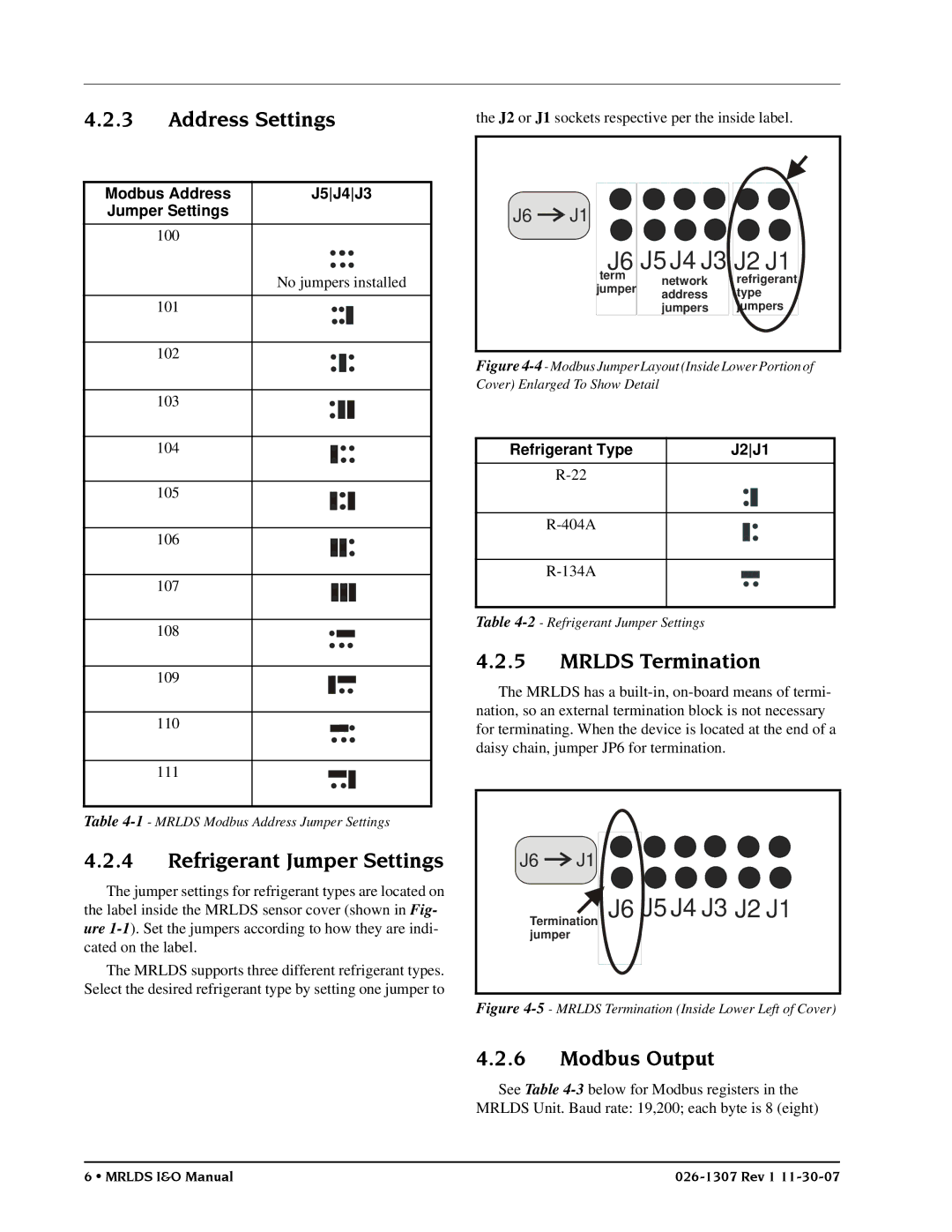
the J2 or J1 sockets respective per the inside label.
Modbus Address | J5J4J3 |
Jumper Settings |
|
100 |
|
| No jumpers installed |
101 |
|
102 |
|
103 |
|
104 |
|
105 |
|
106 |
|
107 |
|
108 |
|
109 |
|
110 |
|
111 |
|
Table
J6 ![]()
![]() J1
J1
J6 J5 J4 J3 J2 J1 | ||
term | network | refrigerant |
jumper | address | type |
| jumpers | jumpers |
Figure 4-4- Modbus Jumper Layout (Inside Lower Portion of Cover) Enlarged To Show Detail
Refrigerant Type | J2J1 |
Table
4.2.5MRLDS Termination
The MRLDS has a
4.2.4Refrigerant Jumper Settings
The jumper settings for refrigerant types are located on the label inside the MRLDS sensor cover (shown in Fig- ure
The MRLDS supports three different refrigerant types. Select the desired refrigerant type by setting one jumper to
J6 ![]()
![]() J1
J1
Termination jumper
J6 J5 J4 J3 J2 J1
Figure 4-5 - MRLDS Termination (Inside Lower Left of Cover)
4.2.6Modbus Output
See Table
6 • MRLDS I&O Manual |