CAUTION: Before installing the Gateway board, verify the jumper JP7 (located near the top center of the board) is set to the “NOR-
MAL” position (not the “TEST” position). Operating the Gateway with the jumper in “TEST” position may cause board damage.
The Gateway Board communicates with the MRLDS via the Modbus network, which is connected to the Gate- way’s “Receiver Bus” network terminal. The Gateway communicates with the E2 via the RS485 I/O Network.
4.3.4Powering the Gateway
Board
Input Voltage | 24VAC, Class 2, |
| 50/60Hz |
|
|
Power | 5VA |
Table
The Gateway board requires 24VAC power from a Class 2
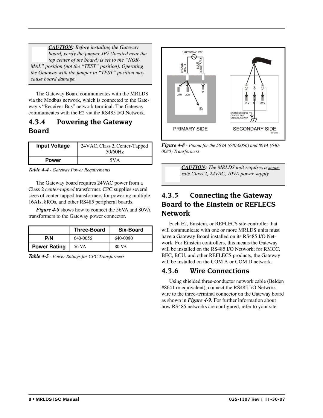
Figure 4-8 shows how to connect the 56VA and 80VA transformers to the Gateway power connector.
|
|
|
|
|
|
P/N | ||
|
|
|
Power Rating | 56 VA | 80 VA |
|
|
|
Table
Figure |
0080) Transformers
CAUTION: The MRLDS unit requires a sepa- rate Class 2, 24VAC, 10VA power supply.
4.3.5Connecting the Gateway Board to the Einstein or REFLECS Network
Each E2, Einstein, or REFLECS site controller that will communicate with one or more MRLDS units must have a Gateway Board installed on its RS485 I/O Net- work. For Einstein controllers, this means the Gateway will be installed on the RS485 I/O Network; for RMCC, BEC, BCU, and other REFLECS products, the Gateway will be installed on the COM A or COM D network.
4.3.6Wire Connections
Using shielded
8 • MRLDS I&O Manual |