bits with no parity and 2 (two) stop bits.
Register | PDU | Logical | Range |
Name | Address | Address |
|
Fault and | 0x0000 | 1 | Under Range |
Module |
|
| 2 (msb) |
State |
|
|
|
|
|
|
|
|
|
| Under Volt- |
|
|
| age 8 (msb) |
|
|
| Temperature |
|
|
| 10 (msb) |
|
|
| Lamp Fail |
|
|
| 40 (msb) |
|
|
| Test Mode |
|
|
| 80 (msb) |
|
|
| Warm Up |
|
|
| Complete |
|
|
| 0 (Lsb) |
|
|
| Cal/Setup |
|
|
| 2 (Lsb) |
|
|
| Factory |
|
|
| Mode |
|
|
| 4 (Lsb) |
|
|
| Trouble |
|
|
| Mode |
|
|
| 8 (Lsb) |
Gas | 0x0001 | 2 | 0 to 40 |
Number |
|
|
|
Gas Con- | 0x0002 | 3 | |
centration |
|
| (ppm) |
Gas |
|
| |
Numbers |
|
| |
|
|
|
Table
4.3MRLDS Gateway
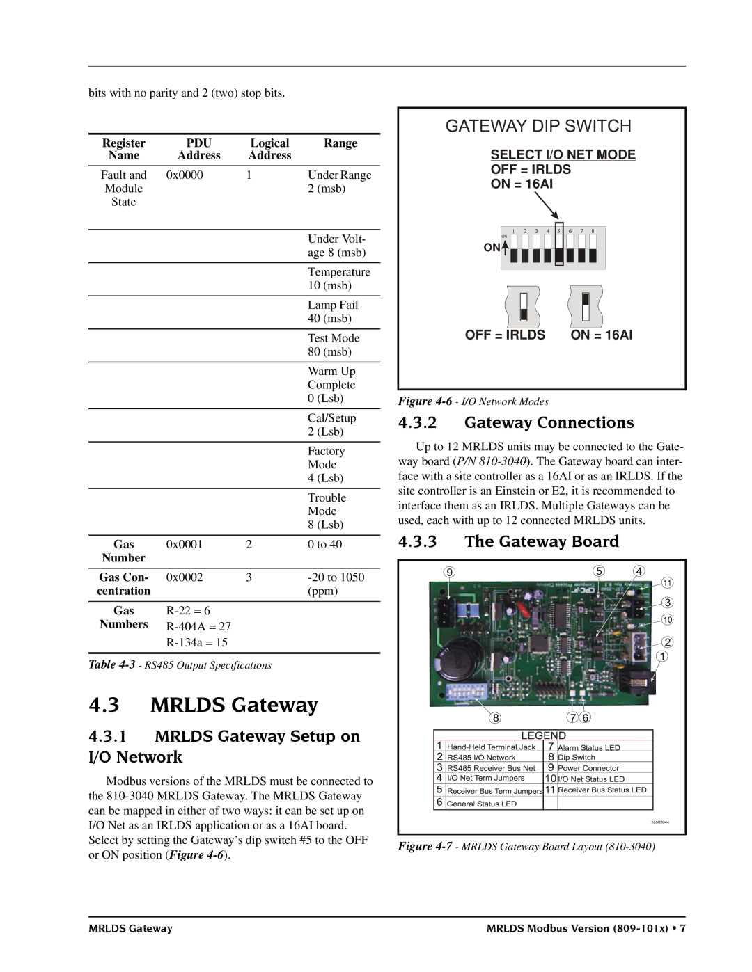
4.3.1MRLDS Gateway Setup on I/O Network
Modbus versions of the MRLDS must be connected to the
SELECT I/O NET MODE
OFF = IRLDS
ON = 16AI
ON![]()
![]()
![]()
![]()
![]()
![]()
![]()
![]()
![]()
![]()
![]()
![]()
![]()
![]()
![]()
OFF = IRLDS ON = 16AI
Figure 4-6 - I/O Network Modes
4.3.2Gateway Connections
Up to 12 MRLDS units may be connected to the Gate- way board (P/N
4.3.3The Gateway Board
Figure |
MRLDS Gateway | MRLDS Modbus Version |