100:CNT: 1
GAS: R134A
ST: NORMAL
ALM: NONE
FAIL I/O NET
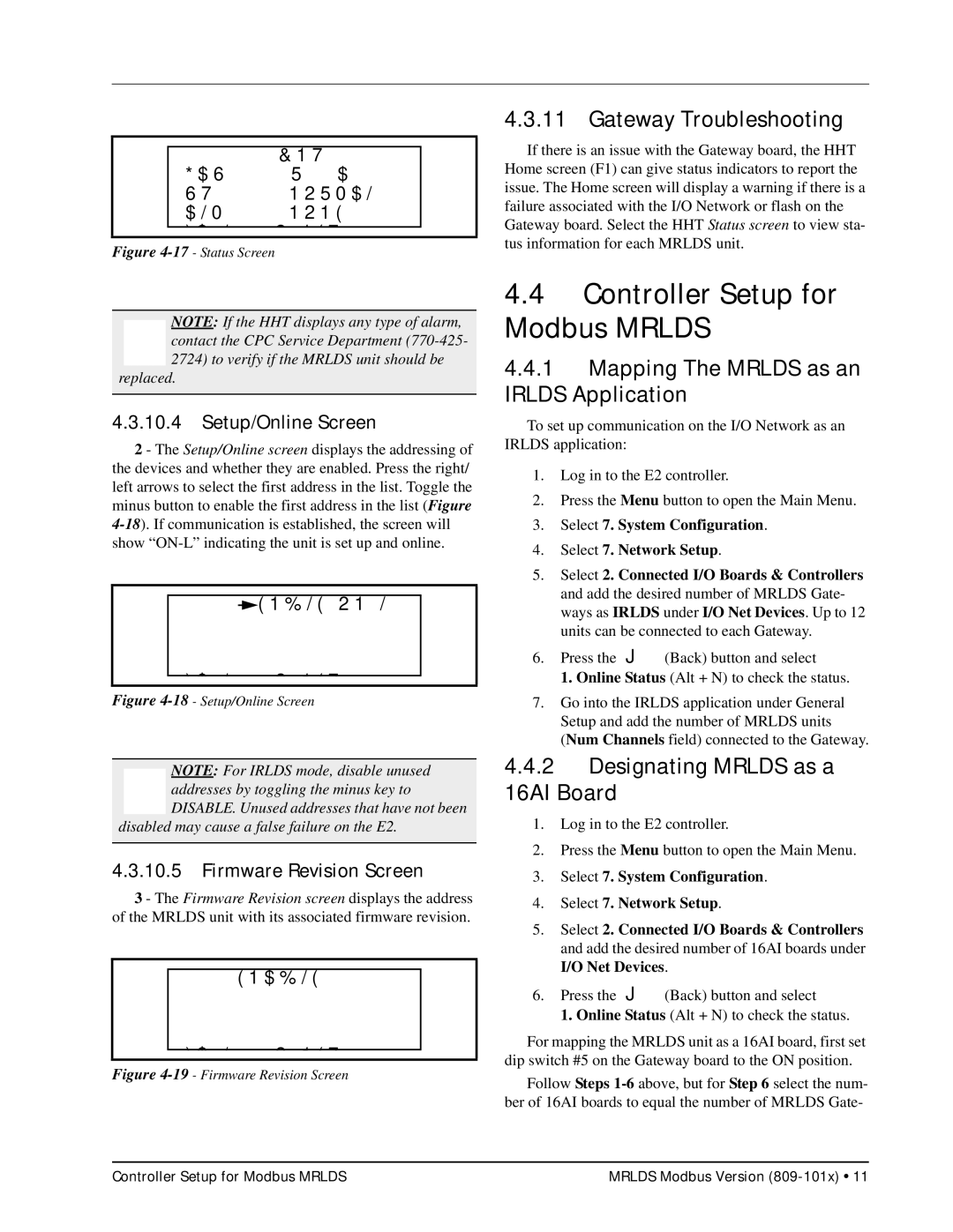
Figure 4-17 - Status Screen
NOTE: If the HHT displays any type of alarm, contact the CPC Service Department
replaced.
4.3.10.4Setup/Online Screen
2 - The Setup/Online screen displays the addressing of the devices and whether they are enabled. Press the right/ left arrows to select the first address in the list. Toggle the minus button to enable the first address in the list (Figure
100:![]() ENBLE
ENBLE
103::
FAIL I/O NET
Figure 4-18 - Setup/Online Screen
NOTE: For IRLDS mode, disable unused addresses by toggling the minus key to DISABLE. Unused addresses that have not been
disabled may cause a false failure on the E2.
4.3.10.5Firmware Revision Screen
3 - The Firmware Revision screen displays the address of the MRLDS unit with its associated firmware revision.
100:ENABLE 1.12
102:
103:
104:
FAIL I/O NET
Figure 4-19 - Firmware Revision Screen
4.3.11 Gateway Troubleshooting
If there is an issue with the Gateway board, the HHT Home screen (F1) can give status indicators to report the issue. The Home screen will display a warning if there is a failure associated with the I/O Network or flash on the Gateway board. Select the HHT Status screen to view sta- tus information for each MRLDS unit.
4.4Controller Setup for Modbus MRLDS
4.4.1Mapping The MRLDS as an IRLDS Application
To set up communication on the I/O Network as an IRLDS application:
1.Log in to the E2 controller.
2.Press the Menu button to open the Main Menu.
3.Select 7. System Configuration.
4.Select 7. Network Setup.
5.Select 2. Connected I/O Boards & Controllers and add the desired number of MRLDS Gate- ways as IRLDS under I/O Net Devices. Up to 12 units can be connected to each Gateway.
6.Press the J(Back) button and select
1. Online Status (Alt + N) to check the status.
7.Go into the IRLDS application under General Setup and add the number of MRLDS units (Num Channels field) connected to the Gateway.
4.4.2Designating MRLDS as a 16AI Board
1.Log in to the E2 controller.
2.Press the Menu button to open the Main Menu.
3.Select 7. System Configuration.
4.Select 7. Network Setup.
5.Select 2. Connected I/O Boards & Controllers and add the desired number of 16AI boards under I/O Net Devices.
6.Press the J(Back) button and select
1. Online Status (Alt + N) to check the status.
For mapping the MRLDS unit as a 16AI board, first set dip switch #5 on the Gateway board to the ON position.
Follow Steps
Controller Setup for Modbus MRLDS | MRLDS Modbus Version |