Figure 2-2 - Attaching and Removing Cover
2.2MRLDS Dimensions
Figure 2-3 - MRLDS Mounting Dimensions
3MRLDS Analog Version (809-100x)
3.1Network Layout
E2 |
|
|
|
|
|
|
|
|
|
|
|
|
|
|
|
|
|
| s |
|
|
|
| r |
|
| e | ||
|
|
|
|
|
| ic |
| ||
|
|
| e |
| v |
| |||
|
| th |
|
| e |
|
| ||
|
| O |
|
| D |
|
|
| |
I/O Net | o |
| t |
|
|
|
| ||
e |
|
|
|
|
| ||||
T | ON |
|
|
|
|
|
| ||
| I/ |
|
|
|
|
|
|
| |
MultiFlex Board |
|
|
|
|
|
|
| ||
MRLDS Units
Figure 3-1 - Analog MRLDS Network Layout Example
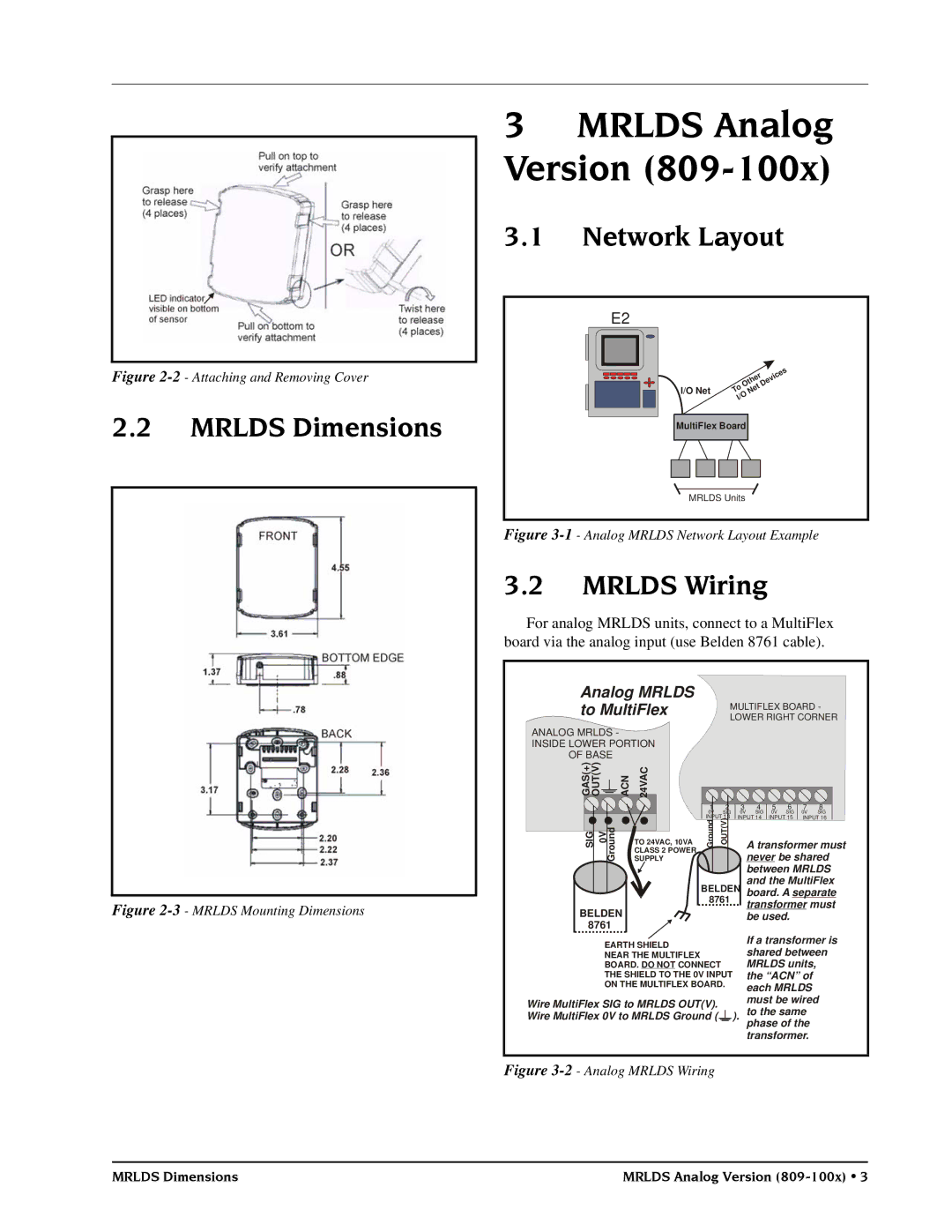
3.2MRLDS Wiring
For analog MRLDS units, connect to a MultiFlex board via the analog input (use Belden 8761 cable).
Analog MRLDS
to MultiFlex MULTIFLEX BOARD -
LOWER RIGHT CORNER
ANALOG MRLDS - |
|
|
|
|
|
|
|
|
|
| |
INSIDE LOWER PORTION |
|
|
|
|
|
|
|
| |||
OF BASE |
|
|
|
|
|
|
|
|
|
| |
)) |
|
|
|
|
|
|
|
|
|
| |
+V | ACN | 24VAC |
|
|
|
|
|
|
|
| |
(( |
|
|
|
|
|
|
|
| |||
ST |
|
|
|
|
|
|
|
|
|
| |
AU |
|
|
|
|
|
|
|
|
|
| |
GO |
|
|
|
|
|
|
|
|
|
| |
|
|
|
| 1 | 2 | 3 | 4 | 5 | 6 | 7 | 8 |
|
|
|
| 0V | SIG | 0V | SIG | 0V | SIG | 0V | SIG |
| uGor |
| SUPPLY | INPUT 13 | INPUT 14 | INPUT 15 | INPUT 16 | ||||
|
| dnu )VT( oGr UO |
| never be shared | |||||||
G | dn |
|
|
|
|
|
|
|
|
|
|
I | 0V |
| TO 24VAC, 10VA |
|
|
| A transformer must | ||||
S |
|
|
|
|
| ||||||
|
|
| CLASS 2 POWER |
|
|
| |||||
|
|
|
|
|
|
| between MRLDS | ||||
|
|
|
| BELDEN | and the MultiFlex | ||||||
|
|
|
| board. A separate | |||||||
|
|
|
| 8761 |
| transformer must | |||||
BELDEN |
|
|
|
| |||||||
|
|
|
| be used. |
|
| |||||
8761 |
|
|
|
|
|
|
|
|
|
| |
EARTH SHIELD | If a transformer is | ||||
shared between | |||||
NEAR THE MULTIFLEX | |||||
BOARD. DO NOT CONNECT | MRLDS units, | ||||
THE SHIELD TO THE 0V INPUT | the “ACN” of | ||||
ON THE MULTIFLEX BOARD. | each MRLDS | ||||
Wire MultiFlex SIG to MRLDS OUT(V). | must be wired | ||||
to the same | |||||
Wire MultiFlex 0V to MRLDS Ground ( |
|
| ). | ||
|
|
|
| phase of the | |
|
|
|
| transformer. | |
Figure 3-2 - Analog MRLDS Wiring
MRLDS Dimensions | MRLDS Analog Version |